5.2. Connection with control box
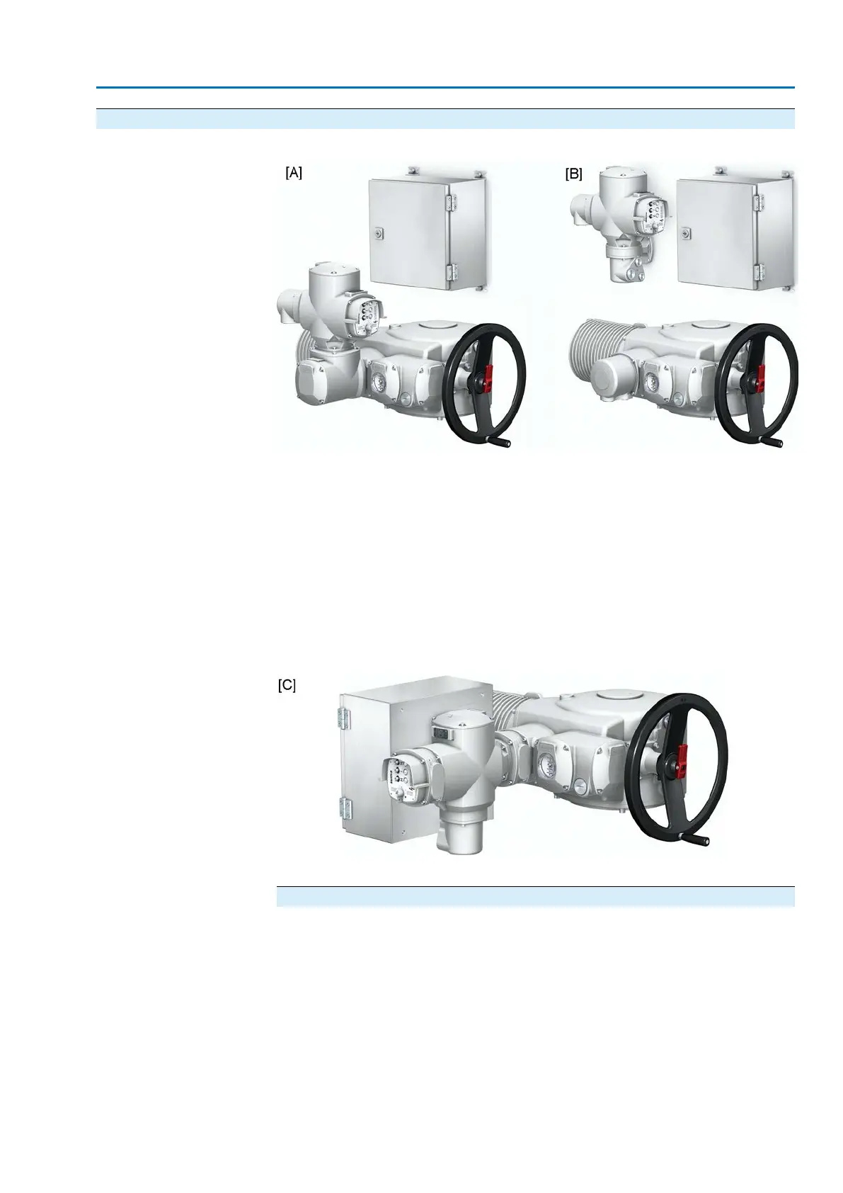
Figure 19: Mounting variants for wall mounted control box
[A] Actuator controls directly mounted
[B] Actuator controls on wall bracket
For actuators with high nominal motor current (AUMA power class switchgear from
category A4), a control box is additionally required. Switchgear (reversing contactors)
will then be installed in the control box and not within the actuator controls.
The control box is usually mounted separately on a wall. In this case, the actuator
controls can either be mounted directly to the actuator [A] or separately on a wall
bracket [B].
As an option the control box directly mounted to the actuator together with the actuator
controls [C].
Figure 20: Mounting the control box to the actuator controls
[C] Actuator controls and control box directly mounted to the actuator
Information on installation with control box
●
Cables and required number of wires are indicated in the wiring diagram.
●
The cable for motor connection has to be shielded.
●
For the power supply cable, fuses have to be provided for short-circuit protection
by the customer.The fuses have to be adapted to the cross section of the cable,
the thermal overload relay in the control box, the switch contacts and the motor
data (refer to motor name plate).
Information
For wall-mounted actuator controls [B], additionally observe <Actuator controls on
wall bracket> chapter.
23
SA 25.1 – SA 48.1 / SAR 25.1 – SAR 30.1
AM 02.1 Electrical connection
 Loading...


