5.4.1. Motor connection
5.4.1.1. Motor connection compartment: open
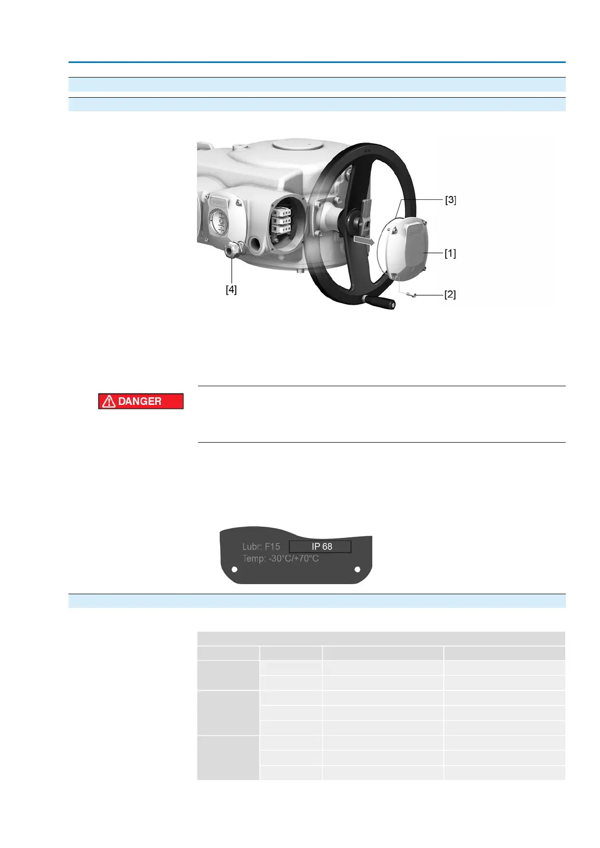
Figure 28: Motor connection compartment: open
[1] Cover
[2] Screws for cover
[3] O-ring
[4] Cable gland
Hazardous voltage!
Risk of electric shock.
→
Disconnect device from the mains before opening.
1. Loosen screws [2] and remove cover [1].
2. Insert cable gland suitable for connecting cable.
➥
The enclosure protection IP… stated on the name plate is only ensured if suit-
able cable glands are used.
Figure 29: Name plate, example with enclosure protection IP68
5.4.1.2. Motor cables: connect
Table 12:
Terminal cross sections and terminal tightening torques
Tightening torquesTerminal cross sectionsSpeedType
2.0 Nm0.5 – 16 mm
2
4 – 22SA 25.1
SAR 25.1
3.5 Nm2.5 – 35 mm
2
32 – 90
1.2 – 2.4 Nm4 – 16 mm
2
4 – 22SA 30.1
SAR 30.1
4.0 – 5.0 Nm10 – 35 mm
2
32 – 45
6.0 – 12 Nm16 – 70 mm
2
63 – 90
1.2 – 2.4 Nm4 – 16 mm
2
4 – 5.6SA 35.1
4.0 – 5.0 Nm10 – 35 mm
2
8 – 22
6.0 – 12 Nm16 – 70 mm
2
32 – 45
29
SA 25.1 – SA 48.1 / SAR 25.1 – SAR 30.1
AM 02.1 Electrical connection
 Loading...


