3. Switch on actuator in direction CLOSE and observe direction of rotation at hollow
shaft [3] or stem [5]:
➥
The direction of rotation is correct if the actuator moves in direction CLOSE
and the hollow shaft in clockwise direction, or the stem moves downward.
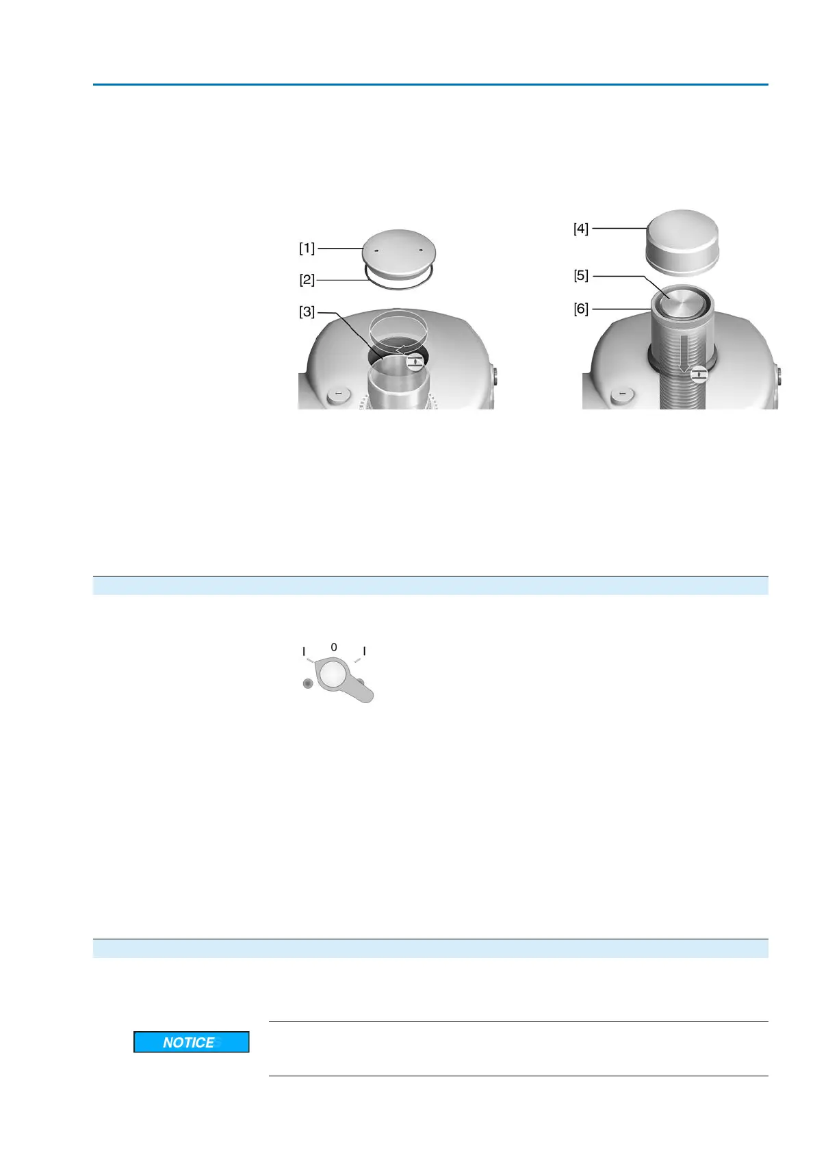
Figure 49: Hollow shaft/stem movement (for “clockwise closing”)
[1] Threaded plug
[2] Seal
[3] Hollow shaft
[4] Protective cap for stem protection tube
[5] Stem
[6] Stem protection tube
4. Correctly fit/screw on threaded plug [1] and seal [2] or protective cap for stem
protection tube [4], fasten thread.
9.5.3. Limit switching: check
1. Set selector switch to position Local control (LOCAL).
2. Operate actuator using push buttons OPEN, STOP, CLOSE.
➥
The limit switching is set correctly if (default indication):
- the yellow indication light is illuminated in end position CLOSED
- the green indication light is illuminated in end position OPEN
- the indication lights go out after travelling into the opposite direction.
➥
The limit switching is set incorrectly if:
- the actuator comes to a standstill before reaching the end position
- the red indication light is illuminated (torque fault).
3. If the end position setting is incorrect: Reset limit switching.
4. If the end position setting is correct and no options (e.g. potentiometer, position
transmitter) are available: Close switch compartment.
9.6. Switch compartment: close
✔
If options (e.g. potentiometer, position transmitter) are available: Only close switch
compartment once all optional equipment has been successfully set.
Danger of corrosion due to damage to paint finish!
→
Touch up damage to paint finish after work on the device.
47
SA 25.1 – SA 48.1 / SAR 25.1 – SAR 30.1
AM 02.1 Commissioning (basic settings)
 Loading...


