→
Operate valve in desired end position (OPEN/CLOSED).
→
Reduce current value: Press push button [S1]
(the current is reduced by 0.02 mA every time the push button is
pressed)
→
Increase current value: Press push button [S2]
(the current is increased by 0.02 mA every time the push button is
pressed)
10.3.3. LED end position signalling: switch on/off
The LED behaviour for end position reached can be set as follows: blinking/continuous
illumination or no illumination. During setting mode, end position signalling is switched
on.
Switching on and off
1. Operate valve in one of the end positions (OPEN/CLOSED).
2. Hold down push buttons [S1] or [S2] for approx. 3 seconds.
➥
End position signalling is switched on or off.
Table 18:
LED behaviour when end position signalling is switched on
LED behaviour in end positionSet output current
LED is blinking slowly
4 mA
LED is blinking fast
0 mA
LED is illuminated
20 mA
10.4. Intermediate positions: set
Actuators equipped with DUO limit switching contain two intermediate position
switches. One intermediate position may be set for each running direction.
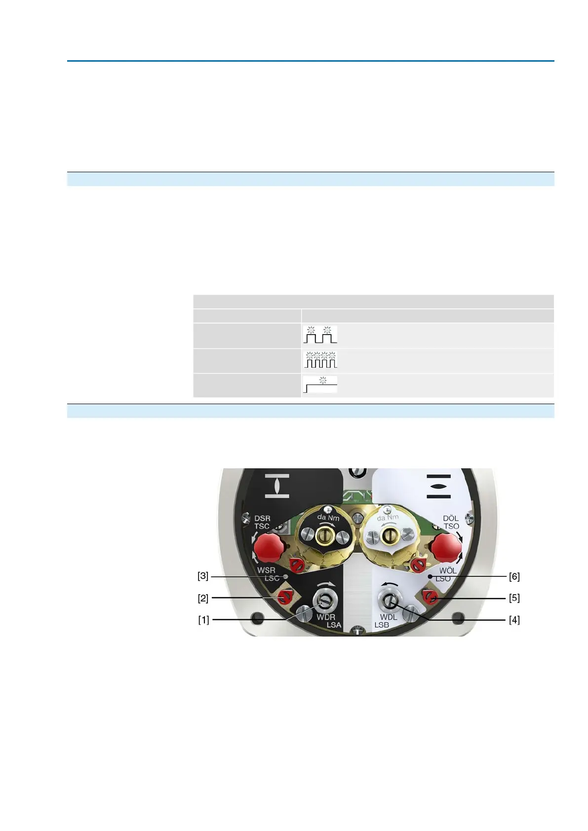
Figure 54: Setting elements for limit switching
Black section:
[1] Setting spindle: Running direction CLOSE
[2] Pointer: Running direction CLOSE
[3] Mark: Intermediate position CLOSED is set
White section:
[4] Setting spindle: Running direction OPEN
[5] Pointer: Running direction OPEN
[6] Mark: Intermediate position OPEN is set
Information After 177 turns (control unit for 2 – 500 turns/stroke) or 1,769 turns (control unit for
2 – 5,000 turns/stroke), the intermediate switches release the contact.
53
SA 25.1 – SA 48.1 / SAR 25.1 – SAR 30.1
AM 02.1 Commissioning (optional equipment settings)
 Loading...


