4.3.1.2. Multi-turn actuator (with output drive type A): mount to valve
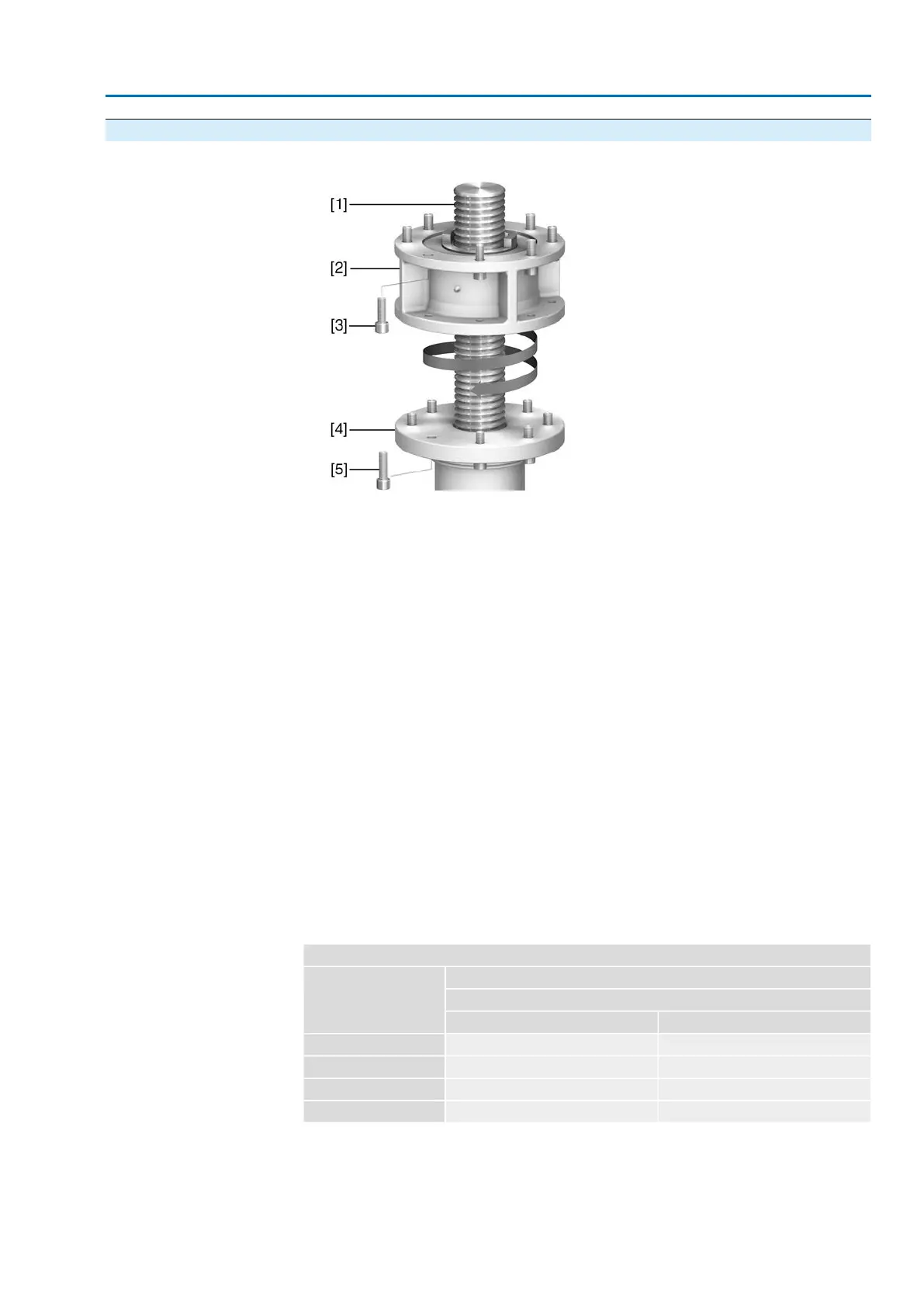
Figure 13: Assembly of output drive type A
[1] Valve stem
[2] Output drive type A
[3] Screws to actuator
[4] Valve flange
[5] Screws to output drive
1. If the output drive type A is already mounted to the multi-turn actuator: Loosen
screws [3] and remove output drive type A [2].
2. Check if the flange of output drive type A matches the valve flange [4].
3. Apply a small quantity of grease to the valve stem [1].
4. Place output drive type A on valve stem and turn until it is flush on the valve
flange.
5. Turn output drive type A until alignment of the fixing holes.
6. Screw in fastening screws [5], however do not completely tighten.
7. Fit multi-turn actuator on the valve stem so that the stem nut dogs engage into
the output drive sleeve.
➥
The flanges are flush with each other if properly engaged.
8. Adjust multi-turn actuator until alignment of the fixing holes.
9. Fasten multi-turn actuator with screws [3].
10. Fasten screws [3] crosswise with a torque according to table.
Table 6:
Tightening torques for screws
Tightening torque [Nm]Threads
Strength class
A2-808.8
200214M16
392431M20
1,4221,489M30
2,4812,594M36
11. Turn multi-turn actuator with handwheel in direction OPEN until valve flange
and output drive A are firmly placed together.
12. Tighten fastening screws [5] between valve and output drive type A crosswise
applying a torque according to table.
17
SA 25.1 – SA 48.1 / SAR 25.1 – SAR 30.1
AM 02.1 Assembly
 Loading...


