11.4. Running indication (blinker transmitter): activate/deactivate
— (Option) —
If the actuator is equipped with a blinker transmitter (wiring diagram designation:
S5), indication lights (OPEN/CLOSE) on the local controls can be used as running
indication. If the running indication is active, the respective indication light blinks
during actuator operation.
The running indication is activated/deactivated via a DIP switch on the logic board.
→
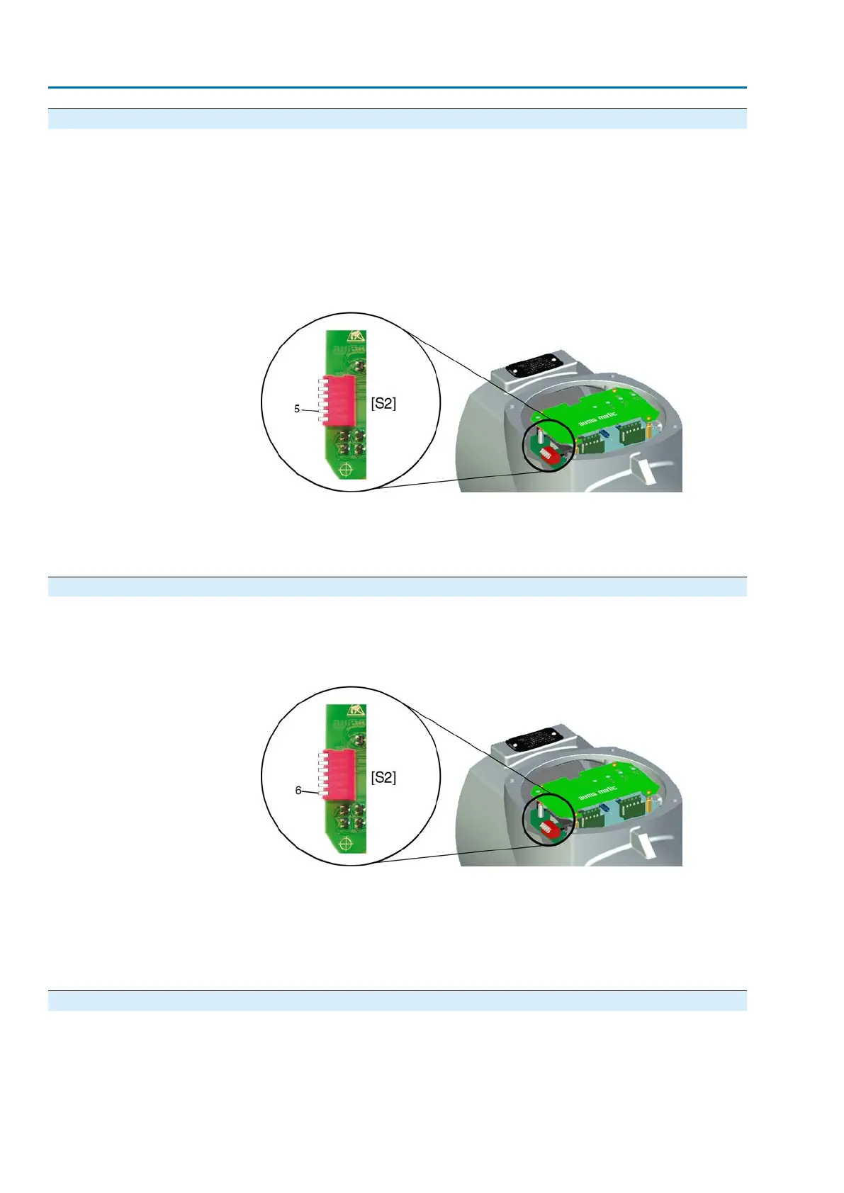
Set running indication (blinker) via DIP switch [S2].
Figure 57: DIP switch on logic board
[S2] 6-way DIP, switch 5
➥
Switch 5 in lower position (position ON): Running indication is deactivated.
➥
Switch 5 in upper position (position OFF): Running indication is activated.
11.5. Torque fault in collective fault signal: activate/deactivate
The torque fault signal is activated/deactivated via a DIP switch on the logic board.
→
Activate/deactivate signal via DIP switch [S2].
Figure 58: DIP switch on logic board
[S2] 6-way DIP, switch 6
➥
Switch 6 in lower position (position ON):The signal "Torque fault in collective
fault signal" is activated.
➥
Switch 6 in upper position (position OFF): The signal "Torque fault in collective
fault signal" is deactivated.
11.6. LEDs for torque fault, phase failure, motor protection
The interface board is equipped with two LEDs for indicating the torque fault, phase
failure and motor protection (thermal fault) fault signals
58
SA 25.1 – SA 48.1 / SAR 25.1 – SAR 30.1
Commissioning – controls settings AM 02.1
 Loading...


