2-wire system3-wire and 4-wire systemsData
0.1 %Impact of power supply
0.1 %Load influence
< 0.1 ‰/KTemperature impact
–60 °C to +80 °CAmbient temperature
2)
Power supply possible via: AC, AM actuator controls or external power supply1)
Depending on temperature range of the actuator: Refer to name plate2)
Setting elements
The EWG is housed in the actuator switch compartment. The switch compartment
must be opened to perform any settings. Refer to <Switch compartment: open>.
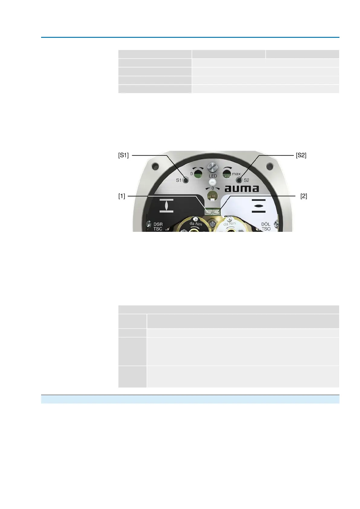
All settings are made via the two push buttons [S1] and [S2].
Figure 53: View on control unit when switch compartment is open
[S1] Push button: Set 0/4 mA
[S2] Push button: Set 20 mA
LED Optical aid for setting
[1] Measuring point (+) 0/4 – 20 mA
[2] Measuring point (–) 0/4 – 20 mA
The output current (measuring range 0 – 20 mA) can be checked at measuring points
[1] and [2].
Table 17:
Short overview on push button functions
FunctionPush but-
tons
→ press simultaneously for 5 s: Activate setting mode[S1] + [S2]
→ press in setting mode for 3 s: Set 4 mA
→ press in setting mode for 6 s: Set 0 mA
→ press in operation for 3 s: Switch on/off LED end position signalling.
→ touch in end position: Reduce current value by 0.02 mA
[S1]
→ press in setting mode for 3 s: Set 20 mA
→ press in operation for 3 s: Switch on/off LED end position signalling.
→ touch in end position: Increase current value by 0.02 mA
[S2]
10.3.1. Measuring range: set
For measuring range setting, voltage must be applied at the position transmitter.
For output current verification, connect a test device for 0 – 20 mA to measurement
points (+/–) (for 2-wire systems, connecting a test device is imperatively required).
51
SA 25.1 – SA 48.1 / SAR 25.1 – SAR 30.1
AM 02.1 Commissioning (optional equipment settings)
 Loading...


