Table 25:
Secondary fuse F3 (internal 24 V DC supply)
AUMA Art.no.:F3G fuse according to IEC 60127-2/III
5 x 20 mmSize
K001.183500 mA T; 250 VVoltage output (power supply unit) = 24 V
K001.183500 mA T; 250 VVoltage output (power supply unit) = 115 V
Table 26:
Secondary fuse F4 (internal AC supply)
1)
AUMA Art.no.:F4G fuse according to IEC 60127-2/III
5 x 20 mmSize
K004.831
K003.131
1.0 A T; 250 V
1.6 A T; 250 V
Voltage output (power supply unit) = 24 V
K003.0210.4 A T; 250 VVoltage output (power supply unit) = 115 V
Fuse for: switch compartment heater, reversing contactor control, PTC tripping device (at 24 V AC
only), at 115 V AC also control inputs OPEN, STOP, CLOSE
1)
Information
Only replace fuses with fuses of the same type and value.
→ After replacing the fuses, tighten local controls again.
Cable damage due to twisting or pinching!
Risk of functional failures.
→
Turn local controls by a maximum of 180°.
→
Carefully assemble local controls to avoid pinching the cables.
12.2.2. Fuses within the control box
Hazardous voltage!
Risk of electric shock.
→
Disconnect device from the mains before opening.
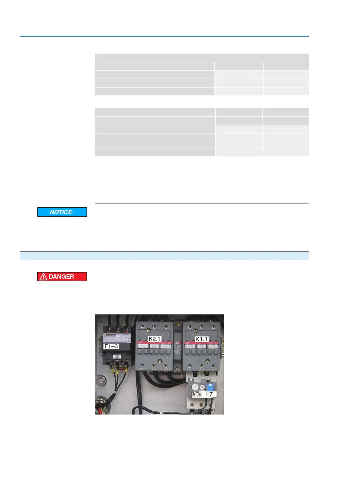
Figure 68: Control box
K2.1, K1.1
Contactors
F1–3
Primary fuses for reversing contactors: Circuit breakers (3-pole isolating switch)
Size: 10 x 38 mm
F7
Thermal overload relay in motor (set nominal current)
68
SA 25.1 – SA 48.1 / SAR 25.1 – SAR 30.1
Corrective action AM 02.1
 Loading...


