Table 22: Further possible settings
[S2–7]Signal type
1)
Behaviour on loss of signal of
DIP 1 2 3 4Actual value E2Setpoint E1E2E1
0 – 5 V4 – 20 mAFail openFail as is
0 – 5 V4 – 20 mAFail openFail close
4 – 20 mA0 – 20 mA
0 – 20 mA
0 – 5 V
0 – 20 mA
0 – 5 V
0 – 10 V
4 – 20 mA0 – 20 mA
0 – 5 V
Fail close
4 – 20 mA0 – 20 mA
0 – 10 V
Fail as is
0 – 20 mA
0 – 5 V
4 – 20 mAFail open
in case of a signal loss, a misinterpretation might be made for 0 – 20 mA, 0 – 5 V or 0 – 10 V, due
to the fact that E1 or E2 could take the value 0 mA even without loss of signal (end position CLOSED
= 0 mA or 0 V).
1)
11.7.3. Adjustment in end positions
The setting described below applies to the standard positioner version, i.e. maximum
setpoint E1 (20 mA) triggers a travel to end position OPEN, minimum setpoint (0/4
mA) triggers a travel to end position CLOSED.
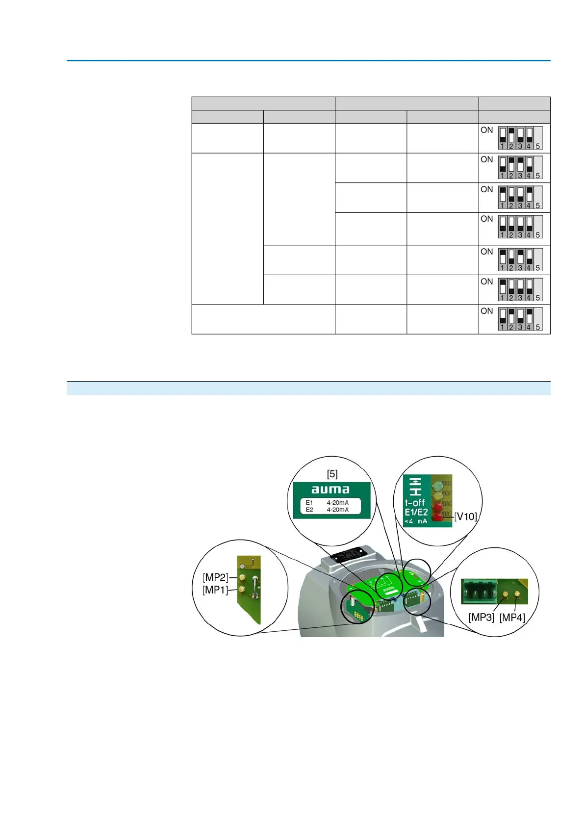
Figure 62: Electronic positioner board
[MP1] Measuring point (–) for actual value E2
[MP2] Measuring point (+) for actual value E2
[MP3] Measuring point (+) for setpoint E1
[MP4] Measuring point (–) for setpoint E1
[5] Label with signal indication
[V10] Red LED: E1/E2 <4 mA
End position CLOSED
1. Set selector switch to position Local control (LOCAL).
2. Move valve to end position CLOSED.
61
SA 25.1 – SA 48.1 / SAR 25.1 – SAR 30.1
AM 02.1 Commissioning – controls settings
 Loading...


