Terminal cross sections and terminal tightening torques
Tightening torquesTerminal cross sectionsSpeedType
4.0 – 5.0 Nm10 – 35 mm
2
4 – 11SA 40.1
6.0 – 12 Nm16 – 70 mm
2
16 – 32
4.0 – 5.0 Nm10 – 35 mm
2
4SA 48.1
6.0 – 12 Nm16 – 70 mm
2
5.6 – 16
1. Remove cable sheathing and insert the wires into the cable glands.
2. Fasten cable gland with the specified torque to ensure required enclosure pro-
tection.
3. Strip wires.
4. For flexible cables: Use end sleeves according to DIN 46228.
5. Connect cables according to order-related wiring diagram.
In case of a fault: Hazardous voltage while protective earth conductor is NOT
connected!
Risk of electric shock.
→
Connect all protective earth conductors.
→
Connect PE connection to external protective earth conductor of connecting
cables.
→
Start running the device only after having connected the protective earth con-
ductor.
6.
Firmly tighten protective earth to PE connection (symbol: ).
7. For shielded cables: Link the cable shield end via the cable gland to the housing
(earthing).
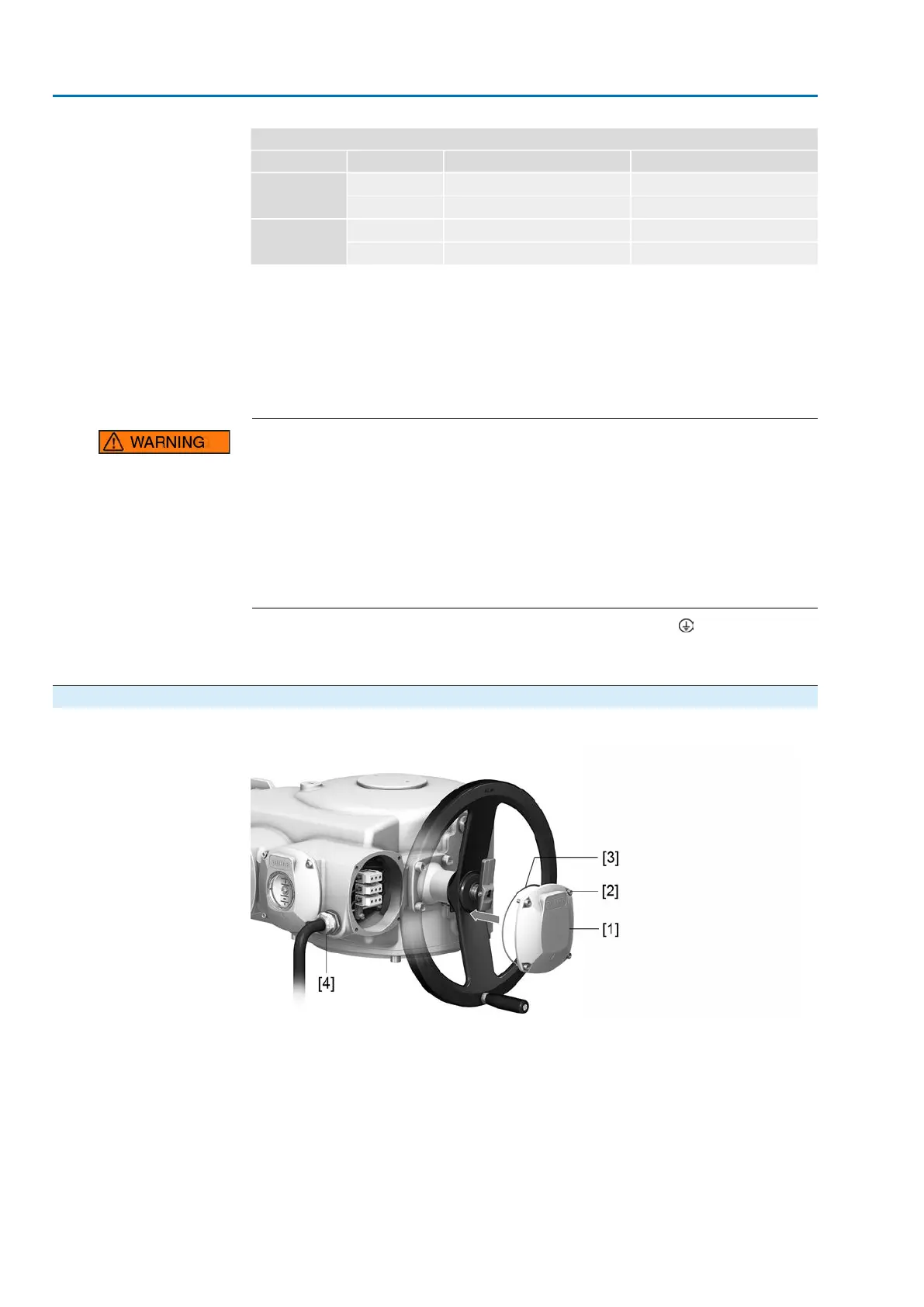
5.4.1.3. Motor connection compartment: close
Figure 30: Close motor connection compartment
[1] Cover
[2] Screws for cover
[3] O-ring
[4] Cable gland
1. Clean sealing faces of cover [1] and housing.
2. Check whether O-ring [3] is in good condition, replace if damaged.
3. Apply a thin film of non-acidic grease (e.g. petroleum jelly) to the O-ring and
insert it correctly.
4. Fit cover [1] and fasten screws [2] evenly crosswise.
30
SA 25.1 – SA 48.1 / SAR 25.1 – SAR 30.1
Electrical connection AM 02.1
 Loading...


