Actuator controls AUMATIC AC 01.1 / ACExC 01.1
DeviceNet Operation instructions
28
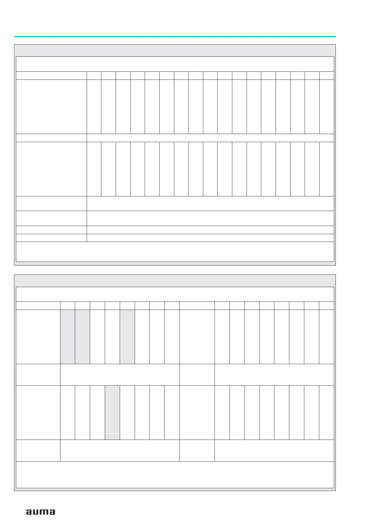
SELECTED PRODUCED PATH = 5
Data length = 14 byte
Bit
1514131211109876543210
Word 1
(actuator signals)
No external controls
—
—
—
—
—
DN1 Anlog In1 loss
Feedback E2 loss
Local sw. position
Remote sw. position
No thermal fault
No loss of phase
LSO (WOEL)
LSC (WSR)
TSO (DOEL)
TSC (DSR)
Word 2 (E2 Feedback)
E2 Feedback (0 – 1 000 per mil)
Word 3
(extended)
Running with
handwheel
Thermal fault
TSC (DSR)
TSO (DOEL)
--
No reaction
Running CLOSE
Running OPEN
Command o.k.
EMERGENCY
MODE
Running CLOSE
Running OPEN
Local sw. position
Selector switch in
REMOTE
LSC (WSR)
LSO (WOEL)
Wort 4
(analogue input 1)
Analogue input 1 (0 – 1 000 per mil)
1)
Wort 5
(analogue input 2)
Analogue input 2 (0 – 1 000 per mil)
1)
Word 6
Reserved
Word 7
Reserved
1) In word 4 and 5, the values of the analogue current inputs of the DeviceNet interface were transmitted. The start and end values can be set at the AUMATIC via
the push-buttons and the display. For further detailed instructions on the indication, operation and setting of the AUMATIC refer to the operation instructions of
the actuator (multi-turn actuator SA(R) … / part-turn actuator SG … with AUMATIC AC ...).
If the measuring values are 0.3 mA below the initial value a loss of signal is indicated. (refer to warning signals 2, byte 16)
Enhanced Input
SELECTED PRODUCED PATH = 6
Data length = 8 byte
Bit
76543210 76543210
Byte 1
(Logical sig-
nals)
Fault ind.
1)
Warning ind.
1)
Running CLOSE
Running OPEN
Not ready ind.
1)
Setpoint position
Closed position
Open position
Byte 2
(Actuator
signals)
TSC (DSR)
TSO (DOEL)
LSC (WSR)
LSO (WOEL)
Local sw. position
Remote sw. position
Loss of phase
Thermal fault
Byte 3
E2 (Feedback)
E2 Feedback 1 (0 – 1 000 per mil) high byte
Byte 4
E2 (Feed-
back)
E2 Feedback 1 (0 – 1 000 per mil) low byte
Byte 5
(Physical ope-
ration)
Running LOCAL
Running REMOTE
Running with
handwheel
Actuator moving
1)
—
Stepping mode
—
Phys.drive break
Byte 6
(Options
part 1)
DN1 dig.in 4
DN1 dig.in 3
DN1 dig.in 2
DN1 dig.in 1
Intermed. pos. 4
Intermed. pos. 3
Intermed. pos. 2
Intermed. pos. 1
Byte 7
(Analogue in-
put 1)
Analogue input 1 (0 – 1 000 per mil) high byte
2)
Byte 8
(Analogue
input 1)
Analogue input 1 (0 – 1 000 per mil) low byte
2)
1) Grey signals are collective signals. They contain the results of a disjunction (or-operation) of other information.
2) Byte 7 and byte 8 transmit the value of the first additional free analogue current input of the DeviceNet interface. The start and end values can be set at the
AUMATIC via the push-buttons and the display. For further detailed instructions on the indication, operation and setting of the AUMATIC refer to the operation
instructions of the actuator (multi-turn actuator SA(R) … / part-turn actuator SG … with AUMATIC AC ...).
If the measuring values are 0.3 mA below the initial value a loss of signal is indicated. (refer to warning signals 2, byte 16)
Process Input Data 1