Run Tests under the System Setup Screens
Use the C-more Micro-Graphic panel’s System Setup Screens to test communication port, PLC
connectivity, the internal beeper and touch screen operation. See Chapter 5: System Setup
Screens for additional details.
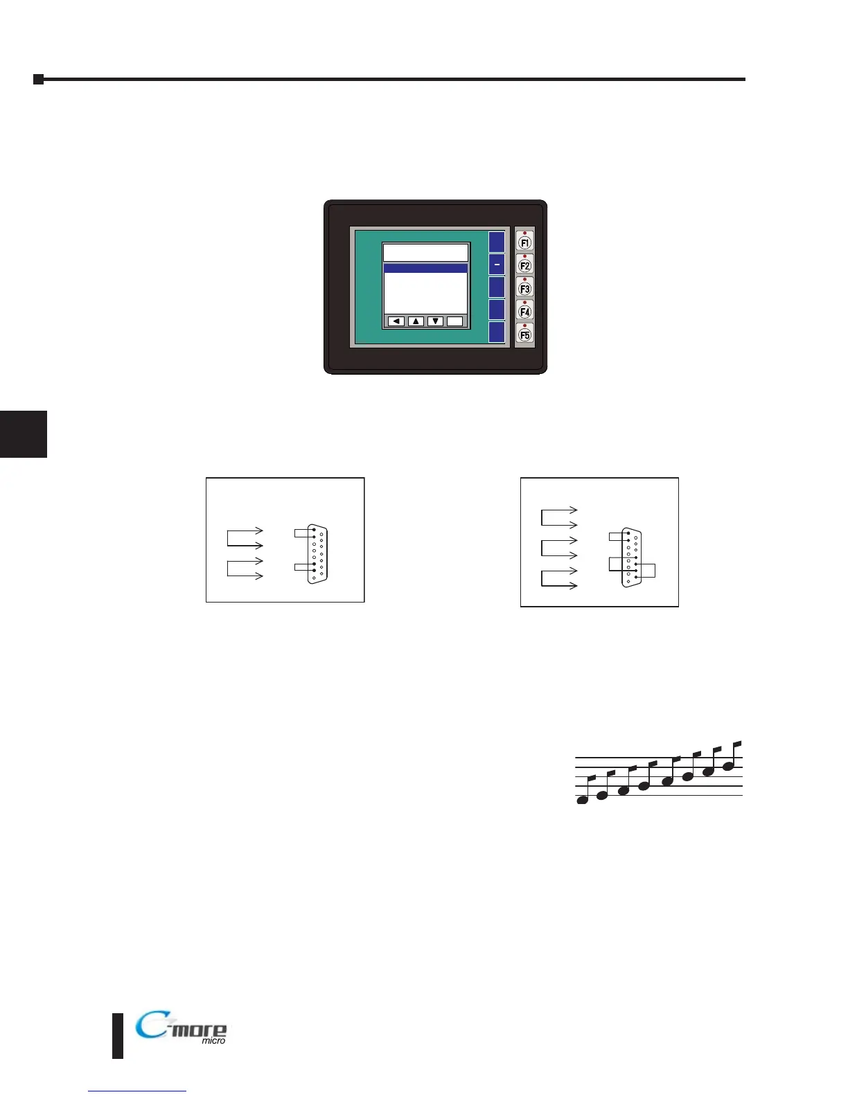
Serial Port - Loop Back Test - Performs a test to verify either the RS-232 or the RS485/422
serial communications functionality from the 15-pin connector (Port 2) on the panel is
operating correctly. A loop back connector inserted into the port is required for proper testing.
Wiring diagrams to build RS-232 and RS-485/422 loop back connectors are shown below.
PLC Enquiry Test - Tests the communications with the selected PLC protocol between the
panel and a connected PLC.
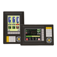
Buzzer Test - Use this option to test the internal audible beeper of the panel.
Touch Panel Test - Tests the response of the touch screen area to contact. This test is used to
make sure the touch screen area is responding properly.
7–4
Chapter 7: Maintenance
 Loading...