EA1-TCL-M Hardware User Manual, 2nd Ed., 10/10
1–10
Chapter 1: Getting Started
1
Step 4 – Install C-more Color Micro-Graphic Panel
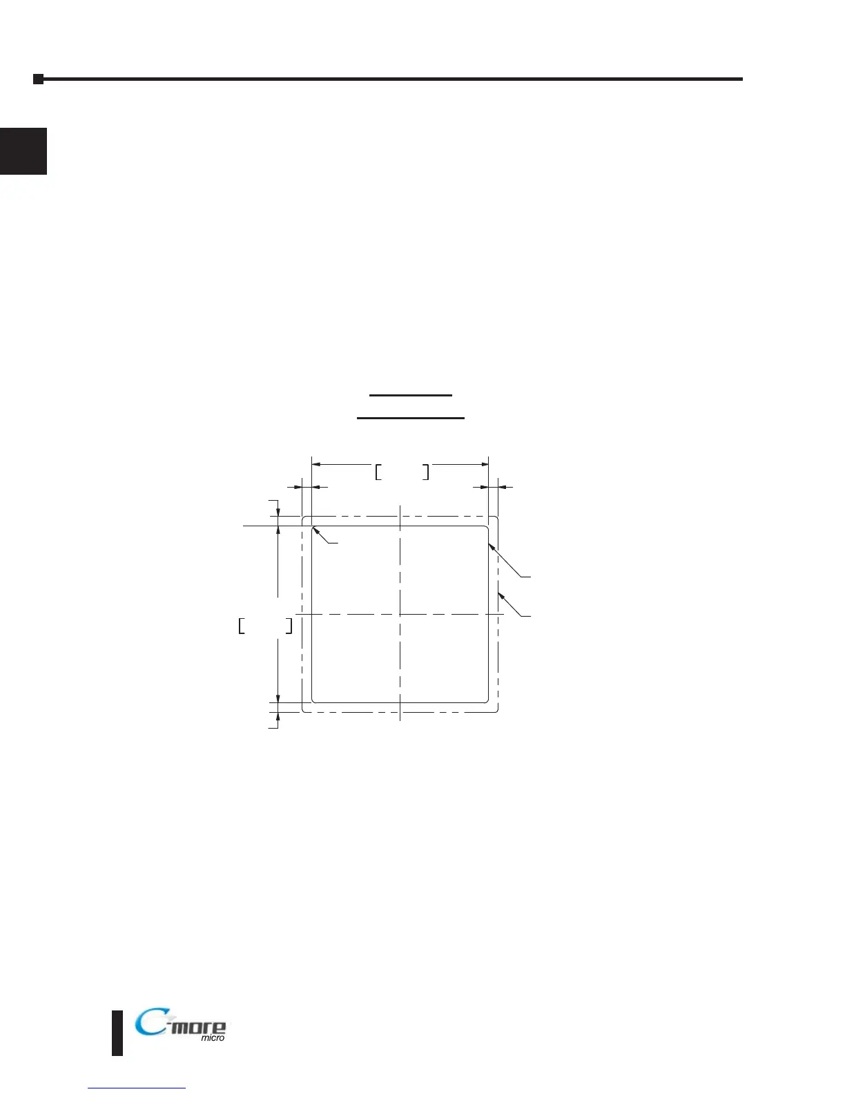
The C-more Micro-Graphic panel can be mounted through a cutout in an enclosure by using
the template that is provided with the panel, or using the dimensions that follow. Cutout
dimensions for the C-more 6” Color Micro-Graphic panel 20-button landscape and 21-button
portrait keypad bezel options are also shown on the next page. The keypad bezels also include
a template that can be used.
The enclosure mounting thickness range for the panels and the keypad bezels is 0.04”–0.2”
[1–5 mm].
The screw torque range for the screws used on the panel mounting clips and the keypad bezel
mounting clips is 21-28 oz-in [0.15-0.2 Nm].
See Chapter 2: Specifications for additional product dimensions and Chapter 3: Accessories
for accessory specifications and dimensions.
EA1-T4CL
Panel Cutout
 Loading...