EA1-TCL-M Hardware User Manual, 2nd Ed., 10/10
1–12
Chapter 1: Getting Started
1
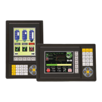
Enclosure Clearances
In all installations, a 1.2” [30mm] minimum clearance is required inside an enclosure for
proper ventilation of the C-more Micro-Graphic panel.
Enclosure Enclosure
1.2
[30.0]
1.5
[38.1]
1.2
[30.0]
2
[50.8]
*
*
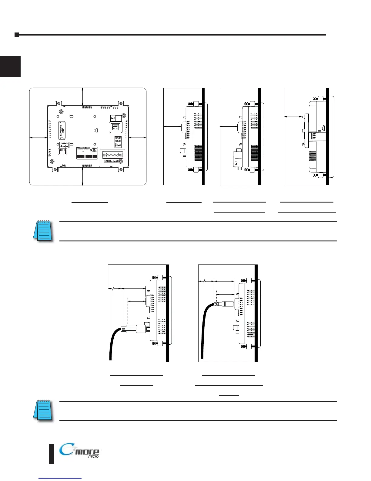
* Additional clearance for cable bend radius typically 1/2” to 1”
Side View with
EA-2CBL
NOTE: Cable connectors are typically longer than 1.2” (30mm). Therefore, in addition to ventilation
requirements, clearance must account for the connector and the cable bend radius.
Enclosure
1.2
[30.0]
Enclosure
1.2
[30.0]
1.2
[30.0]
PU : 2 24V 5W C a s2
I T D
M 7
a e c de * *
01
M DE N CH NA
A1 T CL + e i l n mber
LMOD L EA -T CL
ND CONT. Q.
81
15
9
1.2
[30.0]
Enclosure
units: inches [mm]
Enclosure
1.2
[30.0]
1.2
[30.0]
1.2
[30.0]
Rear View
EA1-T6CL with
EA-MG6-BZ2(P)
Side view
Side View with
EA-ADAPTR-4
Side View with
USB programming
cable
NOTE: Additional clearance inside the enclosure is required when connecting to the 15-pin serial
communications port (Port2) unless the 90 EA-ADPTR-4 is used.
 Loading...