EA1-TCL-M Hardware User Manual, 2nd Ed., 10/10
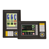
Panel Cutout Dimensions
The C-more 4” and 6” Micro-Graphic panels are mounted into a cutout through the control
cabinet and secured with four (4) mounting clips. The mounting clips are provided with the
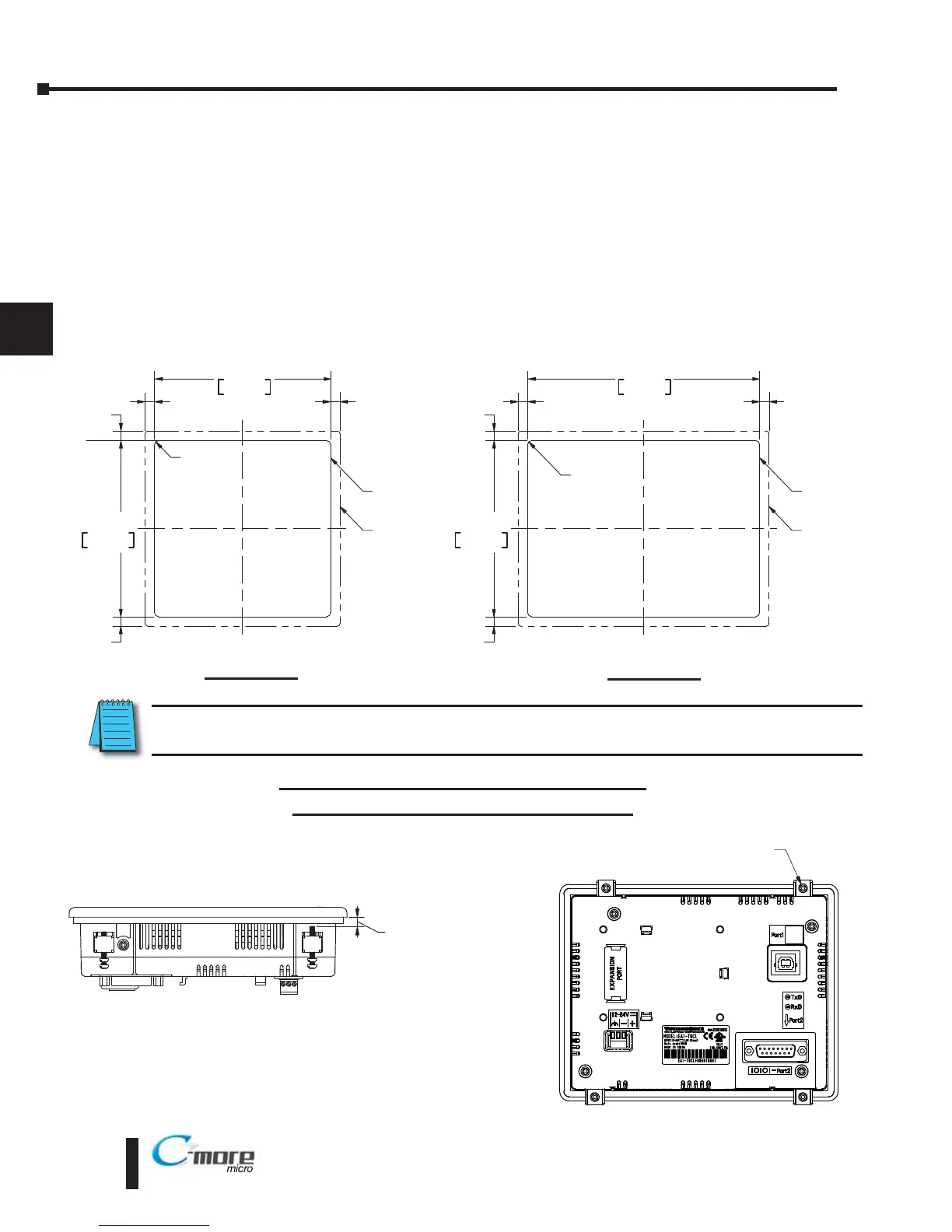
panel. There are slots on each side of the panel’s long dimension that the two tabs on each
mounting clip will match. The mounting clips are held in place by inserting the tabs into the
“T” shaped holes (slots) and then moving the mounting clip toward the rear of the panel to keep
it in place. Next tighten the mounting clip screws to pull the rear of the panel’s bezel to the
control cabinet’s mounting surface. The screws need to be tightened to the torque rating shown
in the illustration below so that the gasket is compressed to form the proper seal between the
panel and cabinet surface.
NOTE: In all installations, a 1.2” [30mm] minimum clearance is required inside an enclosure for proper
ventilation of the C-more Micro-Graphic panel.
 Loading...