EA1-TCL-M Hardware User Manual, 2nd Ed., 10/10
1–8
Chapter 1: Getting Started
1
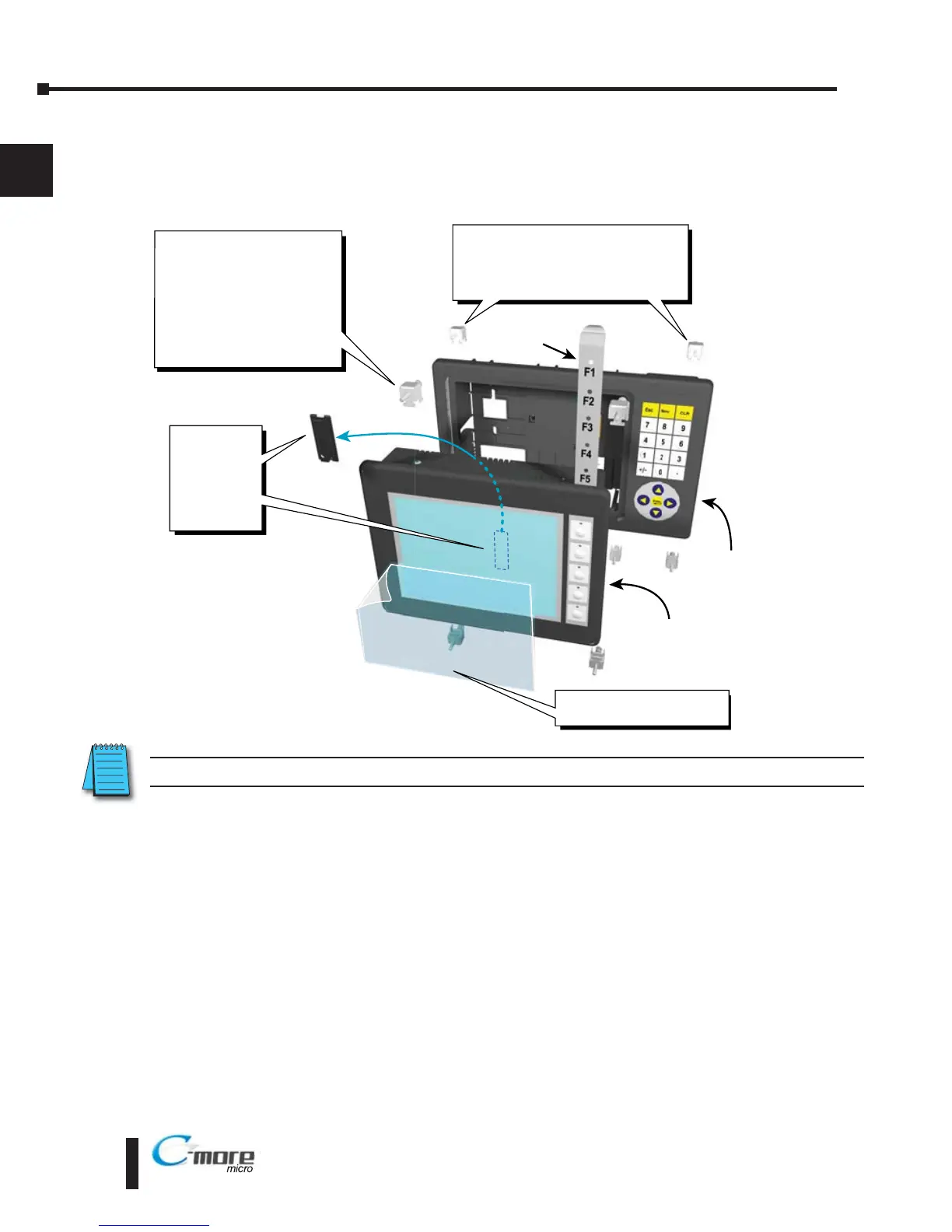
Step 2 – Install Optional Hardware Accessories (EA1-T6CL)
The C-more 6” Micro-Graphic panel can be mounted in an optional 20 or 21 button keypad
bezel. Below is an example of a C-more 6” Micro-Graphic panel being assembled with the
optional EA-MG6-BZ2 20-button Keypad Bezel.
C-more Color 6 Inch
Micro-Graphic Panel
20 Button
Keypad Bezel
EA MG6 BZ2
1. Remove
Expansion
Connector
Protective
Cover from
rear of
panel.
2. Use the (4) Panel Mounting
Clips, EA-MG-BZ2-BRK,
that are supplied with the
panel, to secure panel to
keypad bezel and compress
the gasket between the
panel and the keypad bezel.
Tighten screws to a torque
of 21-28 oz-in [0.15-0.2 Nm].
3. Use (8) Bezel Mounting Clips,
EA-MG-BZ2-BRK, to secure keypad
bezel through enclosure cutout.
Tighten screws to a torque of
21-28 oz-in [0.15-0.2 Nm].
Function
Key Label
Insert
4. Peel Protective Film
from front of panel.
 Loading...