EA1-TCL-M Hardware User Manual, 2nd Ed., 10/10
AutomationDirect CLICK PLC, ProductivitySeries, DirectLOGIC DL05, DL06,
D0-DCM Module & DL105 PLCs
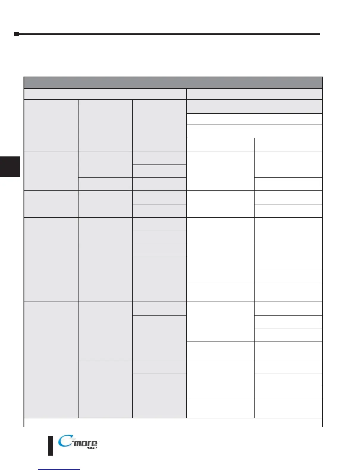
Panel Powered via external power supply, Port2 Communications
Compatibility & Connection Chart
Controller
C-more
Micro-Graphic Panel
Family CPU PLC Port & Type
Panel to PLC Cabling Components Required for
Specific Port and Protocol being used.
External DC Power Supply
Using panel’s Port2
DB 15-pin - female
Protocol(s)
Supported
Components &
Network Type
CLICK
all versions
Port1
RJ12 - 6 pin
AutomationDirect
Modbus (CLICK)
EA-2CBL
RS-232
Port2
RJ12 - 6 pin
Analog CPUs
Port3
Terminal block - 3 pin
* See Diagram 18
RS-485
Productivity Series
all versions
RS-232
RJ12 - 6 pin
AutomationDirect
Productivity3000 Serial
(P3-550)
EA-2CBL
RS-232
RS-232 Port Terminal
block - 3 pin
* See Diagram 19
RS-485
Direct
LOGIC
DL05
all versions
Port 1
RJ12 - 6 pin
K-sequence,
Direct
NET,
Modbus RTU
EA-2CBL
RS-232
Port 2
RJ12 - 6 pin
D0-DCM
Port 1
RJ12 - 6 pin
K-sequence,
Direct
NET,
Modbus RTU
EA-2CBL
RS-232
Port 2
DB15HD
(female)
EA-2CBL-1
RS-232
* See Diagram 1
RS-422
Modbus RTU
* See Diagram 2
RS-485
Modbus only
Direct
LOGIC
DL06
all versions
Port 1
RJ12 - 6 pin
K-sequence,
Direct
NET,
Modbus RTU
EA-2CBL
RS-232
Port 2
DB15HD
(female)
EA-2CBL-1
RS-232
* See Diagram 1
RS-422
Modbus RTU
* See Diagram 2
RS-485
Modbus only
D0-DCM
Port 1
RJ12 - 6 pin
K-sequence,
Direct
NET,
Modbus RTU
EA-2CBL
RS-232
Port 2
DB15HD
(female)
EA-2CBL-1
RS-232
* See Diagram 1
RS-422
Modbus RTU
* See Diagram 2
RS-485
Modbus only
* Note: Wiring Diagrams for user constructed cables start on page 6-24.
 Loading...