Setting Up a VENUE S6L System for the First Time 10
Unpacking and Assembling Basic System Components
Follow the instructions in this section to unpack system components and make basic connections (power, monitor, and keyboard).
After completing this section, proceed to
Activating S6L System Components at Avid.com.
Unpacking
When unpacking and assembling S6L system components, make sure at least two people are available at all times. Team lift all sys-
tem components. Keep cables and other included items organized, making sure to keep them with their associated component after
unpacking.
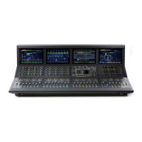
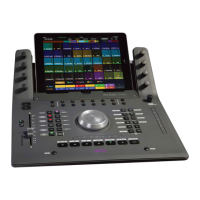
Remove the S6L control surface and other included items from their shipping package, and place it on a table or other stable sur-
face that leaves full access to its front and back panels. Keep its Welcome Pack nearby.
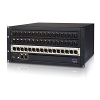
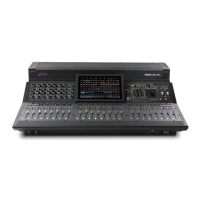
Remove the E6L engine and other included items from their shipping package and place it on a flat surface, leaving full access
to its front and back panels.Do NOT install the included bezel to the front panel of the E6L yet. You will be instructed to install it
later after installing and activating software.
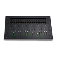
Place any Stage I/O units on a flat surface.
Rack Mounting
You can install the E6L engine, Stage 64, Stage 32, Stage 16, or Local 16 in an enclosure such as a road case. Rack ears for that
purpose are included in their shipping package.
For E6L rack mount instructions, see the E6L Engine Rack Supports.pdf
For I/O unit rack mount instructions, see the S6L Stage IO Rack Supports.pdf.
Connecting Power
Make primary and, if desired, redundant power connections to all S6L system components.
To connect power to the S6L control surface:
1 Connect an included IEC power cable from AC power inlet A on the back panel of the S6L control surface to your power source.
2 For fully redundant power connections, connect the other included IEC power cable from AC power inlet B on the back panel
of the S6L control surface to a secondary power source.
To connect power to the E6L engine:
1 Connect the included IEC power cable from AC power inlet A on the back panel of the E6L engine to your power source.
2 For fully redundant power connections, connect the other included IEC power cable from AC power inlet B on the back panel
of the E6L engine to a secondary power source.
To connect power to the Stage IO unit:
1 Connect the included IEC power cable from an AC power inlet on the back of the Stage IO unit to your power source.
2 For fully redundant power connections, connect the other included IEC power cable from the other AC power inlet on the back
of the Stage I/O unit to a secondary power source.
Disconnecting the Included IEC Power Cables
The IEC power cables included with S6L system devices lock when connected to the AC power in-
lets of S6L system devices, and must be released when disconnecting.
To release an included IEC cable from an AC power inlet on an S6L system device:
Simultaneously slide the two tabs on either side of the connector back, then pull the cable out of
the power inlet.
 Loading...