5-95
Chapter 5. DETAILED DESCRIPTION OF EACH FUNCTION
MODE display setup
The mode related setup items of the parameter setting and mode bank to be
displayed can be set.
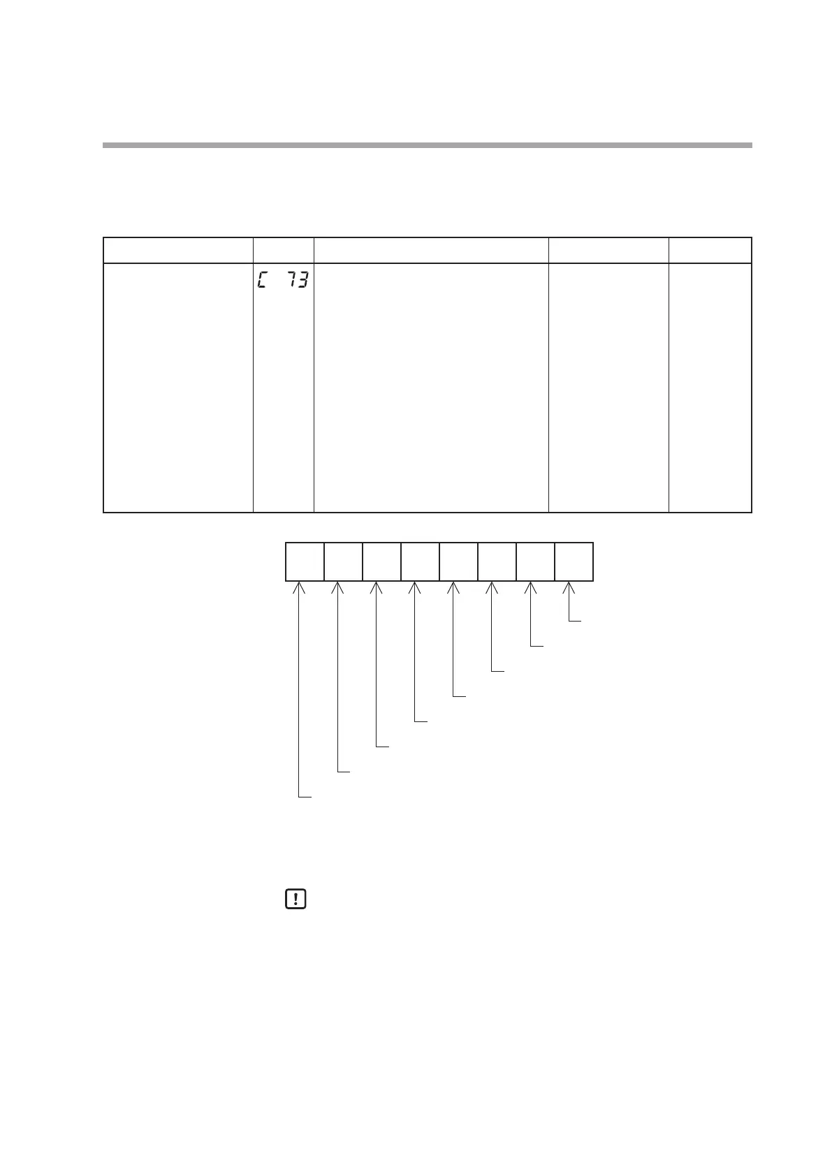
Item (Bank) Display Contents Initial value User level
MODE display setup
(Setup bank)
Whether or not the mode bank setup is
displayed is determined by the sum of the
following weights:
Bit 0: AUTO/MANUAL display
Disabled: 0, Enabled: +1
Bit 1: RUN/READY display
Disabled: 0, Enabled: +2
Bit 2: LSP/RSP display
Disabled: 0, Enabled: +4
Bit 3: AT stop/start display
Disabled: 0, Enabled: +8
Bit 4: Release all DO latches display
Disabled: 0, Enabled: +16
Bit 5: Communication DI1 ON/OFF display
Disabled: 0, Enabled: +32
Other invalid settings, 0, +64, +128
255 Standard,
High function
2
7
2
6
2
5
2
4
2
3
2
2
2
1
2
0
Undened.
Communication DI1 ON/OFF display
Release all DO latches display
AT stop/start display
LSP/RSP display
RUN/READY display
• When using the SLP-C35 Smart Loader Package, not only the numeric value, but
also the bit input can be used to set [
C73
: MODE display setup].
Handling Precautions
• Even though the AUTO/MANUAL display is set at [Displayed], the AUTO/
MANUAL is not displayed when [
CtrL
: Control method] is set at “0” (ON/
OFF control).
• Even though the AT stop/start display is set at [Displayed], the AT stop/
start is not displayed when [
CtrL
: Control method] is set at “0” (ON/OFF
control).
• Even though the LSP/RSP display is set at [Enabled], the LSP/RSP is not
displayed if the model does not provide the RSP input.
 Loading...


