6-27
Chapter 6. LIST OF DISPLAYS AND SETTING DATA
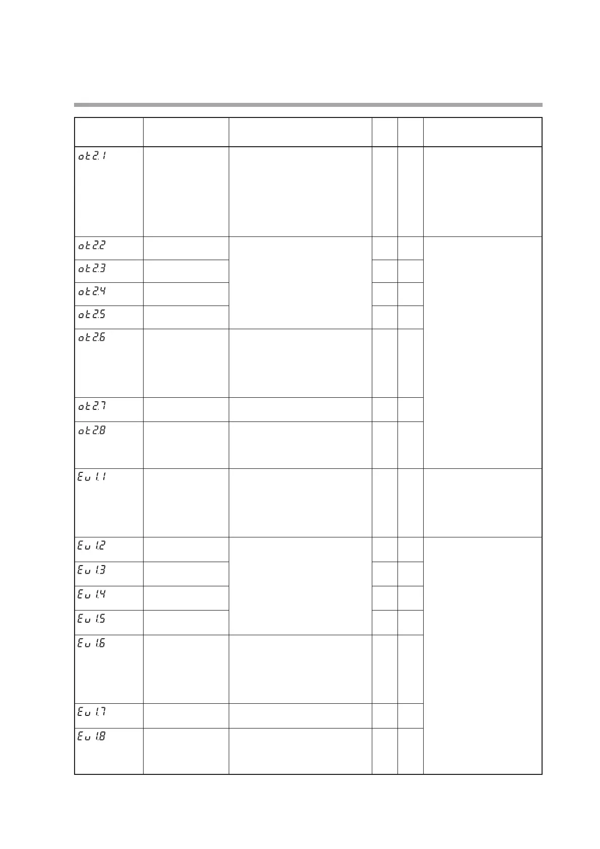
Display Item Contents
Initial
value
User
level
Notes
Control output 2
Operation type
Same as Control output 1 Operation
type.
0: Default output
1: MV1
2: MV2
3 to 6: Function 1 to 4
0 2
Displayed when the control
output of the model is set
to the position proportional
output or the control output
2 of the model is voltage
pulse output.
When using control output 2,
the default output is MV2.
Control output 2
Output assignment A
Same as Control output 1 Output
assignment A to D.
15 2
Displayed when control
output 2 of the model is set
to the voltage pulse output
and the operation type of
control output 2 is set 1 to 4
(
Ot2.
1
> 2).
Control output 2
Output assignment B
0 2
Control output 2
Output assignment C
0 2
Control output 2
Output assignment D
0 2
Control output 2
Polarity A to D
1st digit: Polarity A
2nd digit: Polarity B
3rd digit: Polarity C
4th digit: Polarity D
Same as Control output 1 Polarity
A to D.
The following setting applies to
each digit:
0: Direct
1: Reverse
0000 2
Control output 2
Polarity
0: Direct
1: Reverse
0 2
Control output 2
Latch
0: None
1: Latch (Latch at ON)
2: Latch (Latch at OFF except for
initialization at power ON)
0 2
Event output 1
Operation type
Same as Control output 1 Operation
type.
0: Default output
1: MV1
2: MV2
3 to 6: Function 1 to 4
0 2
Displayed when the optional
model has Event output 1.
When using Event output 1,
the default output is Internal
Event 1.
Event output 1
Output assignment A
Same as Control output 1 Output
assignment A to D.
2 2
Displayed when the optional
model has Event output 1
and the operation type of
Event output 1 is set 1 to 4
(
Ev
1.
1
> 2).
Event output 1
Output assignment B
0 2
Event output 1
Output assignment C
0 2
Event output 1
Output assignment D
0 2
Event output 1
Polarity A to D
1st digit: Polarity A
2nd digit: Polarity B
3rd digit: Polarity C
4th digit: Polarity D
Same as Control output 1 Polarity
A to D.
The following setting applies to
each digit:
0: Direct
1: Reverse
0000 2
Event output 1
Polarity
0: Direct
1: Reverse
0 2
Event output 1
Latch
0: None
1: Latch (Latch at ON)
2: Latch (Latch at OFF except for
initialization at power ON)
0 2
(Continue on next page.)
 Loading...


