3-47
Chapter 3 Starting and Stopping this Device
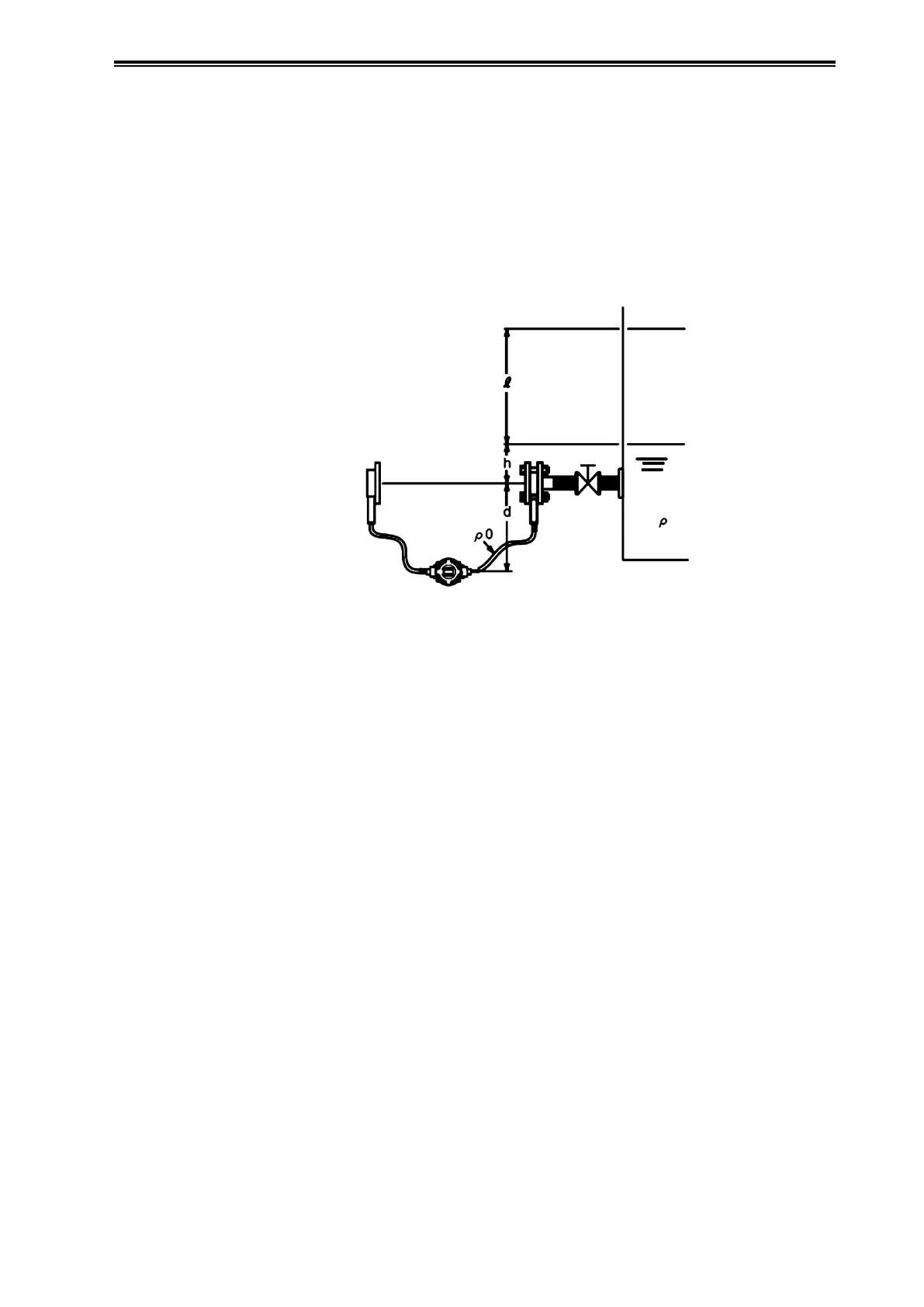
(4) Calculation Example Using the JTE Model
Calculation of the setting range is described below.
In this calculation, density and distance are represented by the following symbols. In addition,
density is assumed to be constant during liquid level measurement.
ρ: Specific gravity of liquid in tank
ρ
0
: Specific gravity of sealed liquid
l: Distance between the 100% liquid level and the 0% liquid level (measurement range)
h: Distance between the 0% liquid level and the high pressure side output port
d: Distance between the high pressure side output port and the transmitter
100% Liquid Level
Open Tank
0% Liquid Level
High Pressure
Side Flange
Low Pressure Side Flange
Figure 3-16. Open Tank
* Here, attach the low pressure side flange at the same height as the high pressure side
flange.
0% liquid level differential pressure
LRV = h×ρ+d×ρ
0
- d×ρ
0
100% liquid level differential pressure
URV = l×ρ+h×ρ
= (l+ h)×ρ+ d×ρ
0
- d×ρ
0
Accordingly,
Low limit LRV: hρ
High limit URV: (l+ h)ρ
is the range to set.
 Loading...