4-8
Chapter 4 Maintenance and Troubleshooting of this Device
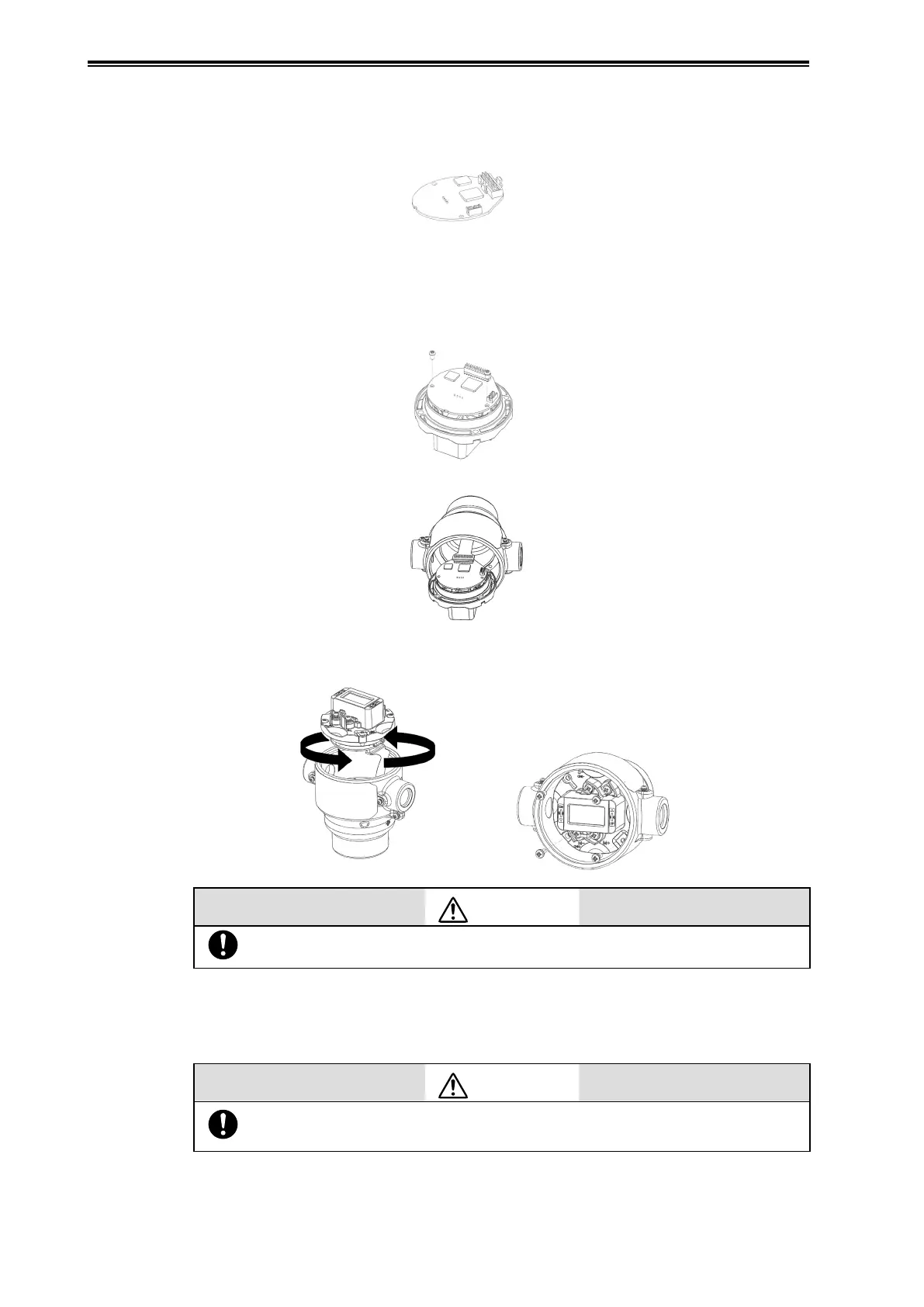
Mount terminal board assembly
(1)
Remove the connector cover from the FPC connector. Assemble the connector cover to a new
electronics module.
(2)
Assemble the electronics module to the indicator/terminal board assembly.
(3)
Fix the electronics module with the 2 screws and connect the LCD connector to the electronics
module.
Tightening torque: 0.6±0.1N·m
(4)
Assemble the FPC connector to the electronics module.
(5)
Mount the indicator/terminal board assembly with 2 rotations not to damage the flexible
printed circuit board (FPC).
Caution
“S+” and “S-” terminals should be in the upper side.
(6)
Fix the indicator/terminal board assembly with 4 screws.
Tightening torque: 1.2±0.1N·m
(7)
Assemble the case cover to the body. Always lock the cover.
Caution
Tighten the cover firmly.
Any looseness may result in water ingress. Refer to 4-2-1.