1-6
Chapter 1 Functionality, Configuration, and Structure of this Device and CommStaff
(iv) External zero adjustment indicators
If the (optional) external zero adjustment functionality is in effect, its operating status is displayed
as follows.
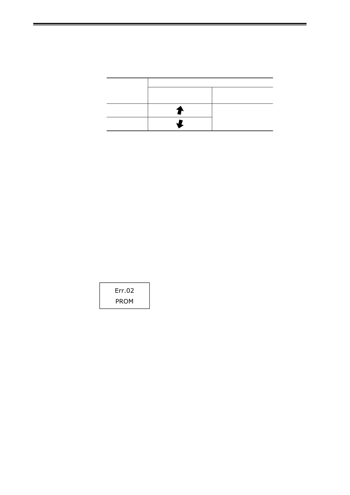
Table 1-3. External Zero Adjustment Operating Status
Adjustment
Status
Indicator
Up and Down Arrows
16-Segment
Indicators
Output rising
ZERO.ADJ
Output falling
(v) Key symbol indicator
When the key symbol is displayed, write protection is in effect. For information regarding write
protection, see section "3-1-2 Settings Confirmation".
(vi) Flag symbol indicator
If diagnostic history information is being retained in the transmission unit, the flag symbol
is displayed. For information regarding items which are retained as history, see section "4-3-2
Diagnostics History Display".
(vii) Display update symbol indicator
Indicates that the transmission unit is operating.
(viii) Transmitter information indicators
Error numbers and error items representing the status of the transmitter's self-diagnostics are
respectively displayed in the upper indicator section (main indicators) and the lower indicator
section (16-segment indicators).
Example:
For information regarding the meaning of the display contents, see section "4-4 Troubleshooting".