INSTALLATION
OIC INSTALLATION
I-E96-192-5A 3 - 9
IIOIC422 Console Setup and Installation
The OIC and OIS consoles are similar, except the OIC console
has no floppy disk drives or network interface unit. The cabi-
net size and installation are the same. Figure 3-4 shows the
dimensions.
Before the OIC console cabinet is set into place in a control
room, insure that the floor is level in the area where the cabi-
nets will be set. Make sure the location can accommodate the
console. Figure 3-4 shows the console cabinet and anchoring
dimensions.
Adjust the leveling screws on all cabinets and connecting
tables until the monitor bezel of each cabinet lines up. The lev-
eling screws adjust 25.6 millimeters (1.05 inches). After secur-
ing the cabinets, put the tables on the cabinets and lock them
into place by sliding the red handle above the front access door
to the right until it stops at the bottom of the slot.
The tabletops are adjustable. The brackets supporting the
tabletops are bolted through oversize holes. Loosen the bolts
and move the top up to 6.35 millimeters (0.25 inches) up,
down, forward or back toward the cabinet to line up the table-
top.
Two chrome table alignment pins shipped inside the brass
bushings located on each side of each tabletop. When two
tabletops are lined up, push the pins outward into the bushing
of the table to the right of the cabinet. Tighten the three bolts
on each tabletop support bracket. Figure 3-5 shows the key-
board table. Figure 3-6 shows the 15 degree wedge table
dimensions, and Figure 3-7 shows the 45 degree wedge table
dimensions.
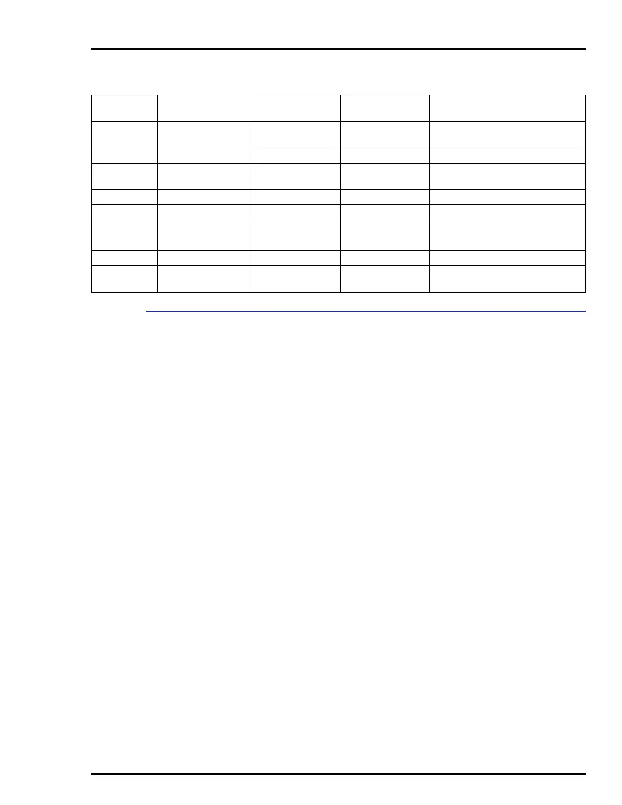
10 6639212A1 AC power Power in on chassis P1on power supply
AC IN on chassis
11 6639213A1 PFI sense P3 on IIMKM02A P3 on power supply
12 6639637A1 Keyboard data P10 on keyboard
interface board
J3 on chassis (inside)
13 6640778A2 Touch screen J5 on chassis 1 port on the OIC CPU
14 6640857A1 Keyboard signal P8 on IIMKM02A J2 on chassis (inside)
15 6642341A1 Mouse J3 on chassis Mouse port on OIC CPU
16 6642342A1 Touch screen Touch screen board J5 on chassis
17 Power cable Power AC IN on OIC CPU AC OUT on chassis
18 1949448A1 Video (RGB) Monitor port on
OIC CPU
RGB on table top chassis
Table 3-2. IIOIC421 Tabletop Cable Connections
(continued)
Figure 3-3
Cable No.
Cable Number Cable Name Connect From Connect To