COMPONENT DESCRIPTION AND REPLACEMENT
POWER ENTRY PANEL
6 - 10 I-E96-192-5A
®
IIOIC424 Panel Mount
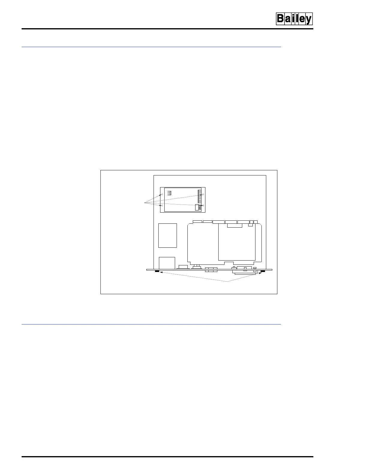
To remove the power supply from an IIOIC424 panel mounted
model see Figure 6-8 and follow these steps:
1. Remove power.
2. To remove the power entry panel, remove the two chassis
screws on the upper edge of the back panel and carefully slide
the unit out far enough to access the power supply mounting
screws. It is not necessary to remove the monitor.
3. Mark and disconnect the wires on the power supply.
4. Remove the four screws from the outside bottom of the
chassis fastening the power supply to the chassis.
POWER ENTRY PANEL
The power entry panel is used on all OIC models except the
IIOIC421 tabletop. Location and part numbers of the power
entry panels used on the OIC consoles vary depending on the
model. The power entry panel contains the incoming AC power
terminals and system circuit breakers along with ports for
connecting peripheral devices and terminals for alarm contact
outputs. The power entry panel also contains the system reset
switch and the degaussing switches for the monitors. Refer to
Table 6-1 for the power entry panel part numbers.
On the IIOIC422 console model, use the upper degauss switch
to correct picture distortion due to magnetic fields on the
screen of the upper (swivel mounted) monitor. Use the lower
Figure 6-8. Power Supply Removal for IIOIC424
Panel Mount Console
POWER SUPPLY
MOUNTING SCREWS
ON BOTTOM OF
CHASSIS
CHASSIS
SCREWS (2)
TP35534A