COMPONENT DESCRIPTION AND REPLACEMENT
IIMKM02A MULTIBUS KEYBOARD MODULE
6 - 2 I-E96-192-5A
®
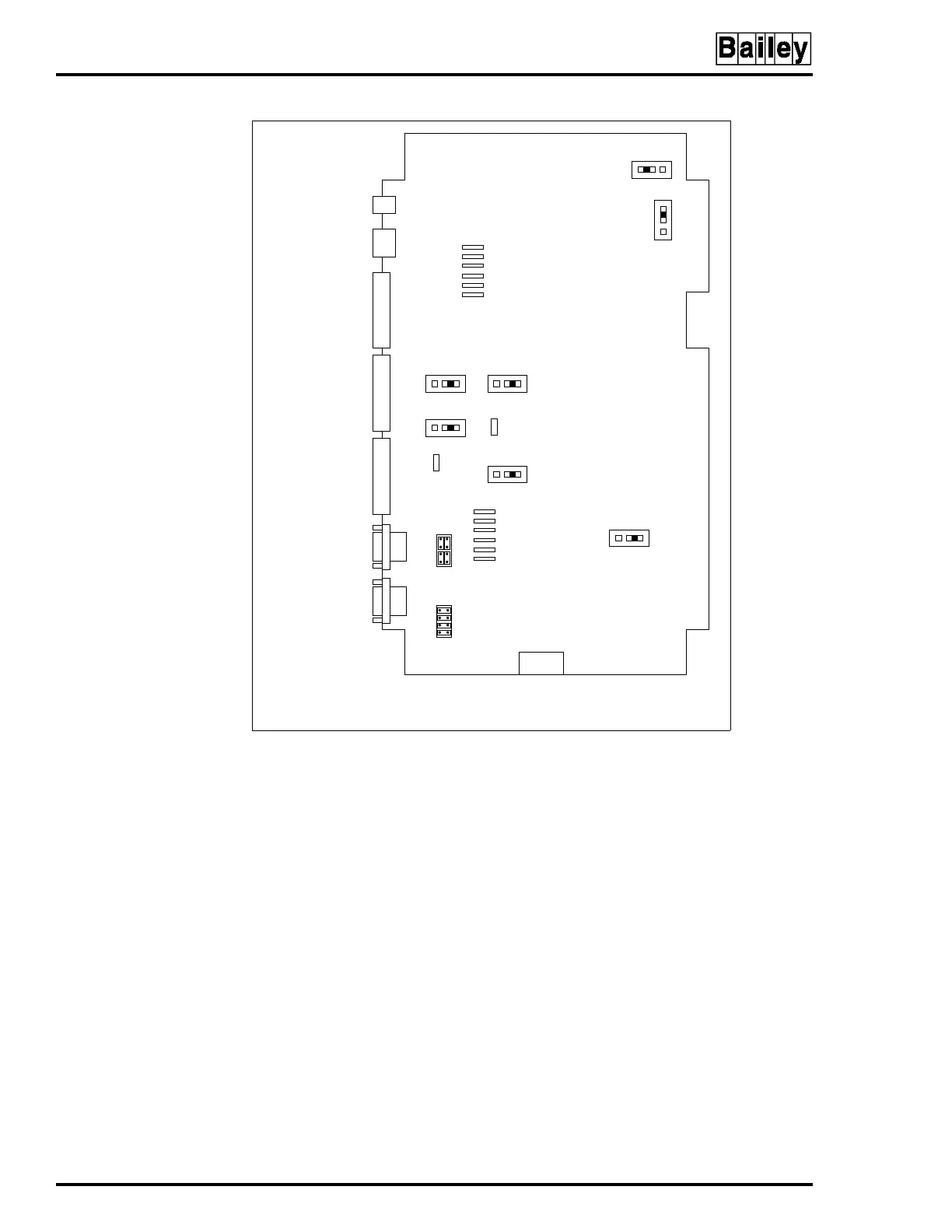
Jumpers J1 and J2 control serial ports one (P8) and two (P9).
Connecting the eight pins horizontally configures the serial
port for data to be transmitted from the MKM module on pin
three of the connector and received from the connected device
on pin two of the connector. Connecting the eight pins verti-
cally as shown for P9 in Figure 6-1 configures the serial port
for data to be transmitted from the MKM module on pin two of
the connector and received from the connected device on pin
three of the connector.
Jumper J3 resets the OIC multibus card cage when the MKM
watchdog timer circuit times out. Set the jumper to J3 pins
one and two for OIC reset on time-out. Set the jumper to J3
pins two and three for no OIC reset on time-out. Factory
default is no reset on time-out.
Jumper J4 allows the option of disabling the power supply
out-of-tolerance (OOT) signal to reset the MKM module. Set the
Figure 6-1. IIMKM02A Multibus Keyboard Module
TP80551A
POWER CONNECTOR FOR
IIMKM02A WHEN USED ON THE
IIOIC421, IIOIC423 AND IIOIC424.
NOTUSEDINIIOIC422.
TO PORT 0
ON CPU
TO KEYBOARD
PORT ON CPU
TO ADP AND KEYBOARD
INTERFACE BOARD
TO TERMINAL
BLOCK ON POWER
ENTRY PANEL
TO KEYBOARD
INTERFACE BOARD
TO RESET SWITCH ON
POWER ENTRY PANEL
TO PFI ON
POWER SUPPLY
P3
J4
J5
P15
P14
P17
P18
J3
P16
P6
P7
P8
P9
P5
P4
123
123
123
123
123
123
3
2
1
J9 J7
J6
J8
J2
J1