COMPONENT DESCRIPTION AND REPLACEMENT
POWER SUPPLY REMOVAL
6 - 6 I-E96-192-5A
®
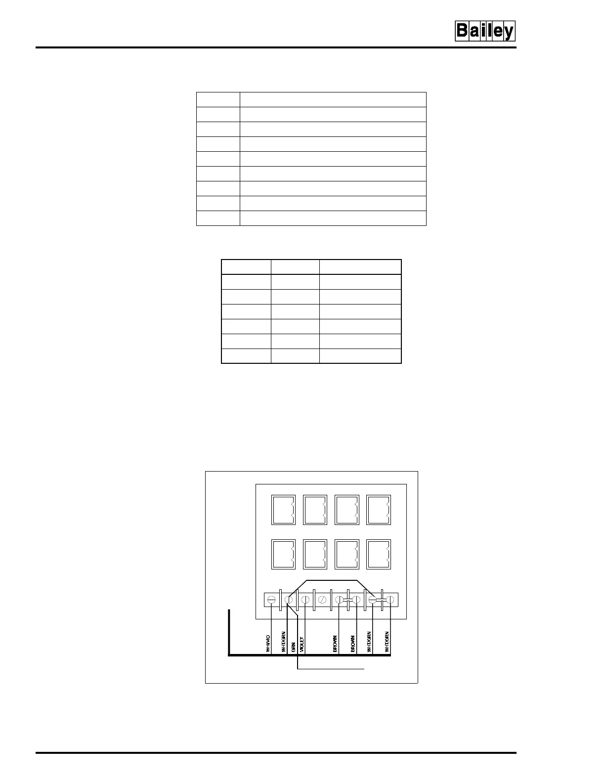
Refer to Section 3 for cable part numbers and connection
information. Figure 6-4 shows the connections from the power
supply to the DC distribution board.
NOTE:
The power supply in the consoles operates on both 120 volts
and 240 volts. The power supply is voltage autosensing and has no
voltage select jumpers.
Table 6-2. DC Distribution Board Socket Connections
Socket Console Connection
P1 IIMKM02A (IIOIC423 only)
P2 —
P3 Keyboard interface board
P4 IIADP02
P5 Backplane (IIOIC422 only)
P6 Backplane (IIOIC422 only)
P7 Fans (card cage and door) (IIOIC422 only)
P8 Fan (monitor)
Table 6-3. DC Distribution Board Pin Outs
Terminal Socket Description
1 1 +12V
22Common
3 3 -12V
4 4 No connection
5-6 5 +5V
7-8 6 Common
Figure 6-4. Connections to DC
Distribution Board
1
2
3
4
5
6
1
2
3
4
5
6
1
2
3
4
5
6
1
2
3
4
5
6
1
2
3
4
5
6
1
2
3
4
5
6
1
2
3
4
5
6
1
2
3
4
5
6
TP80553A
TO E1 CHASSIS
GROUND ON PEP
TO P2 ON
POWER SUPPLY
6638710A9
DC DISTRIBUTION BOARD 6638235A1
P2
P1
P4
P3
P6
P5
P8
P7
12 876543
 Loading...