COMPONENT DESCRIPTION AND REPLACEMENT
OPERATOR INTERFACE DEVICES
6 - 20 I-E96-192-5A
®
IIOIC423 ENVIRONMENTAL MODEL
To remove the keyboard interface assembly from an IIOIC423
environmental console, follow these general guidelines.
1. Open the front door and turn off the main circuit breaker
on the power entry panel to shut off power to the console. Ver-
ify power is removed.
2. Label and disconnect all cables to or from the keyboard
interface assembly.
3. Remove the four screws securing the keyboard interface
assembly to the power entry panel.
4. Remove the keyboard interface assembly.
5. Refer to Figure 6-14 for SW1 settings for the new keyboard
interface assembly.
IIOIC424 PANEL MOUNTED MODEL
To remove the keyboard interface assembly from the panel
mounted model, follow these general procedures:
1. Turn off the power to the panel mounted model. Verify
power is removed.
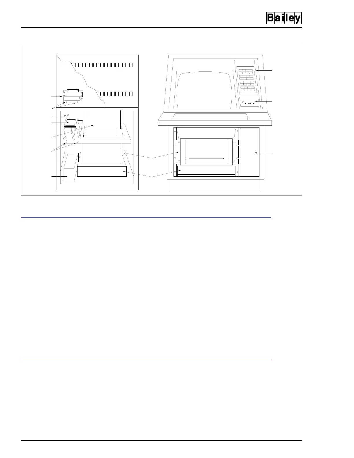
Figure 6-15. Keyboard Interface Assembly Removal for IIOIC422 Consoles
REAR VIEW
POWER SUPPLY
KEYBOARD
INTERFACE
ASSEMBLY
ANNUNCIATOR
DISPLAY PANEL
OPERATOR
KEYBOARD
INTERFACE
PANEL
POWER
ENTRY
PANEL
TP80556A
CPU
MULTIBUS
CARD CAGE
MONITOR
POWER ENTRY
PANEL
POWER SUPPLY
MOUNTING
SCREWS
BRACKET
SCREWS (2)
DC DISTRIBUTION
BOARD
FRONT VIEW