INSTALLATION
OPERATOR INTERFACE DEVICES
I-E96-192-5A 3 - 25
IIADP02 Annunciator Display Panel
The IIADP02
annunciator display panel provides 32 LEDs and
pushbuttons. This panel is provided with the IIOIC422 console
model and can be added to the IIOIC424 panel mount model.
It is not used on the IIOIC423 environmental or IIOIC421
tabletop models. Each LED is assigned to a tag. Each push-
button may be assigned to a display or a key macro. When a
tag goes into an alarm condition, the assigned LED turns on.
Once the LED is activated, it will continue flashing until the
alarm condition is removed. Press the pushbutton to call the
display or key macro assigned to it.
Up to four annunciator display panels can be driven from an
MKM module. Maximum cable length is 4.5 meters (15 feet).
Refer to Figure 3-20 for the dipswitch configuration. Refer to the
operation and configuration instruction for more information.
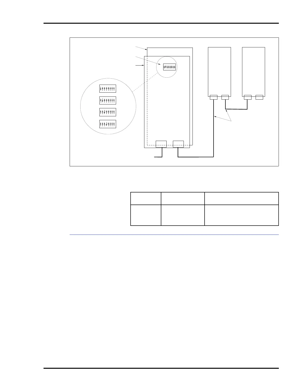
Figure 3-19. IIADP01 Annunciator Display Panel SW1 Settings
TP35494B .
TO AUX PORT ON
KEYBOARD
INTERFACE BOARD
P1
BACK OF
ADP PANEL
ADDRESS
SWITCH
PC BOARD
ADDRESS SWITCH
SETTINGS
SW1
12345678
12345678
12345678
12345678
OPEN
OPEN
OPEN
OPEN
SW1
SW1
SW1
ADP
1
ADP
2
ADP
3
ADP
4
P1
SW1
1948978A1
P1
P2
P2 P2
ADP
2
ADP
3
ADP
4
12345678
OPEN
Table 3-6. IIADP01 Board Connections
Cable
Number
Connect From Connect To
1948978A1 P1 or P2 on ADP 2
board
AUX 1 port on keyboard interface
board, or to:
P1 or P2 on ADP 3 board