COMPONENT DESCRIPTION AND REPLACEMENT
OPERATOR INTERFACE DEVICES
6 - 18 I-E96-192-5A
®
IIOIC424 panel mount consoles, the keyboard interface assem-
bly is below the monitor and above the CPU. Refer to Table 6-1
for part numbers. Refer to Section 7 when replacing fuses for
fuse part numbers.
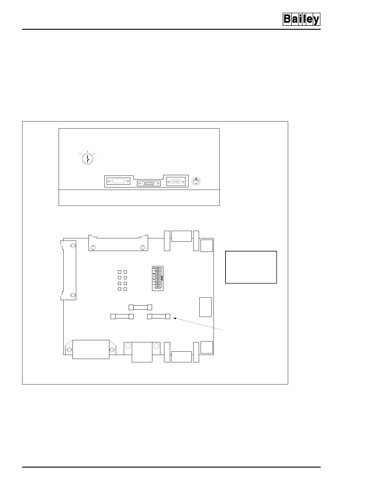
The keyboard socket is for the operator keyboard supplied with
the OIC consoles (Figure 6-14). The AUX 1 port is for a table-
top annunciator display panel. The auxiliary keyboard connec-
tor is for an engineering keyboard. Connector P9 is not used.
Figure 6-14. Keyboard Interface Assembly (IIOIC422 Model)
MOUSE/
TRACKBALL
AUX 1
PORT
KEYBOARD
AUX
KBD
OFF
TUNE CONFIG
KEYBOARD INTERFACE ASSEMBLY FRONT VIEW
KEYBOARD INTERFACE ASSEMBLY CONNECTOR BOARD
TO P5 ON
MKM BOARD
P1
J2
1
VIO
BRN
BLK
2
BLU
RED
YEL
5V
GND
+12V
-12V
SW1
F2
F1 F3
J1
P3
KEYBOARD
AUX 1 PORT
AUX KBD
MOUSE/TRACKBALL
P4
P5
P6
P2
P8
ASSY 6638238-1
SW1 SWITCHES
5,6AND7ARE
CLOSED (ON)
TP P3 ON DC
DISTRIBUTION
BOARD. NOT USED ON
IIOIC421 OR IIOIC424.
F1, F2 AND F3
ARE 2-A, 250-V
FAST BLOW
TO P7 ON
MKM BOARD
AND TO P2 ON
ADP BOARD
P9
NOT USED
P10
TO MOUSE
PORT ON CPU
CAUTION: SWITCHES 5, 6
AND 7 ARE CLOSED (ON).
SWITCHES 1 THROUGH 4
AND 8 ARE OPEN (OFF). IF
THEY ARE NOT SET
CORRECTLY, DAMAGE TO
THECPUMAYRESULT.
TP80554A