INSTALLATION
OPERATOR INTERFACE DEVICES
I-E96-192-5A 3 - 23
7 6638720A6 Monitor bezel
controls
Connector on monitor Brightness on bezel
Contrast on bezel
Degauss on chassis
8 6642341A1 Mouse P10 on keyboard inter-
face assembly
Mouse port on
OIC CPU
9 6639352A1 I/O power P2 on keyboard inter-
face assembly
I/O power port on
chassis
10 6640112A2 AC power P2 on power supply Line filter and E1 (chassis
ground)
11 6640113A1 PFI sense P3 on IIMKM02A J2 on power supply
12 6640164C1 DC power P1 on power supply P16 on IIMKM02A and
KYBD
ADP
FAN ports on chassis
13 6640778A2 Touch screen Connector on touch
screen board
1 port on the OIC CPU
14 Power cable Power AC in on OIC CPU Power out on chassis and
line filter
15 1949448A1 Video (RGB) Monitor port on
OIC CPU
RGB on monitor
16 6639031A1 Filter AC IN on monitor Line filter
17 1947950A7 Power AC power AC IN on chassis
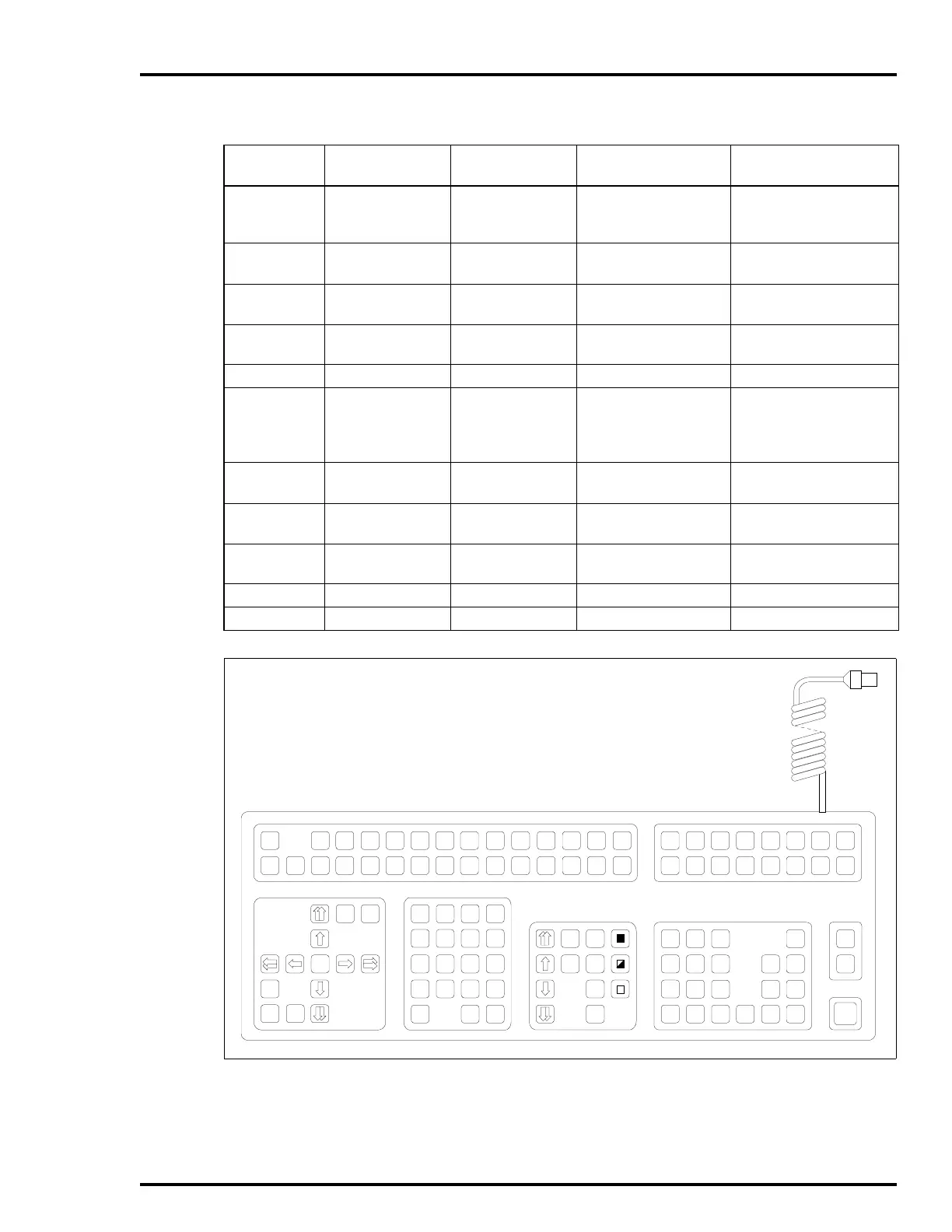
Figure 3-17. Operator Keyboard
Table 3-5. IIOIC424 Panel Mount Cable Connections
(continued)
Figure 3-16
Item No.
Cable Number Cable Name Connect From Connect To
A
SHIFT
SHIFT
LOCK
PAN
HOME
TAB
TAB
BACK
CURSORCURSOR
ZOOM
SPACE
N
B
O
C
P
D
Q
F
S
&
7
$
4
!
1
(
.
;
8
%
5
@
2
)
0
:
9
"
6
#
3
<
=
?
/
'
*
,
+
>
-
E
R
G
T
H
U
I
V
J
W
K
X
L
Y
M
AREA
1
AREA
9
AREA
2
AREA
10
SYSTEM
STATUS
SUMM
COM'D
LINE
MENU
MARK
RECALL
ALARM
SUMM
GENL
FCTNS
MENU
OUT RATIO
MAN/
AUTO
CASCADE
SET
CMPTR
BACK
FORW D
DISPLAY
SUMM
MISC
MENU
PREV
PAG E
NEXT
PAG E
GROUP/
GRAPHIC
HELP
DETAILS
OP
PAR AMS
CANCEL
TUNE
DISPLAY
SWITCH
AREA
3
AREA
11
AREA
4
AREA
12
AREA
5
AREA
13
AREA
6
AREA
14
AREA
7
AREA
15
ACK
ALARM
PAGE
ACK
SILENCE
AREA
8
AREA
16
Z
TP35387
ENTER ESCCLEAR