Chapter 2 Disassembly Process
2-3
CLM W6_CLM HD6 Jan 31, 2012
2-3 Disassemble I/O COVER
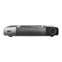
1. Unscrew 17 black screws (yellow
circle) and 8 hex screws (red circle)
to disassemble I/O cover.
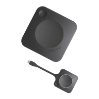
2. Unplug 2 connectors (red square).
Repair note: - Please arrange the two wires,
when assemble I/O cover.
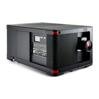
3. Use a tweezers to open 1 clip (yellow
square).
4. Remove front IR sensor board.
5. Unscrew 2 screws (yellow circle),
remove IR cover.
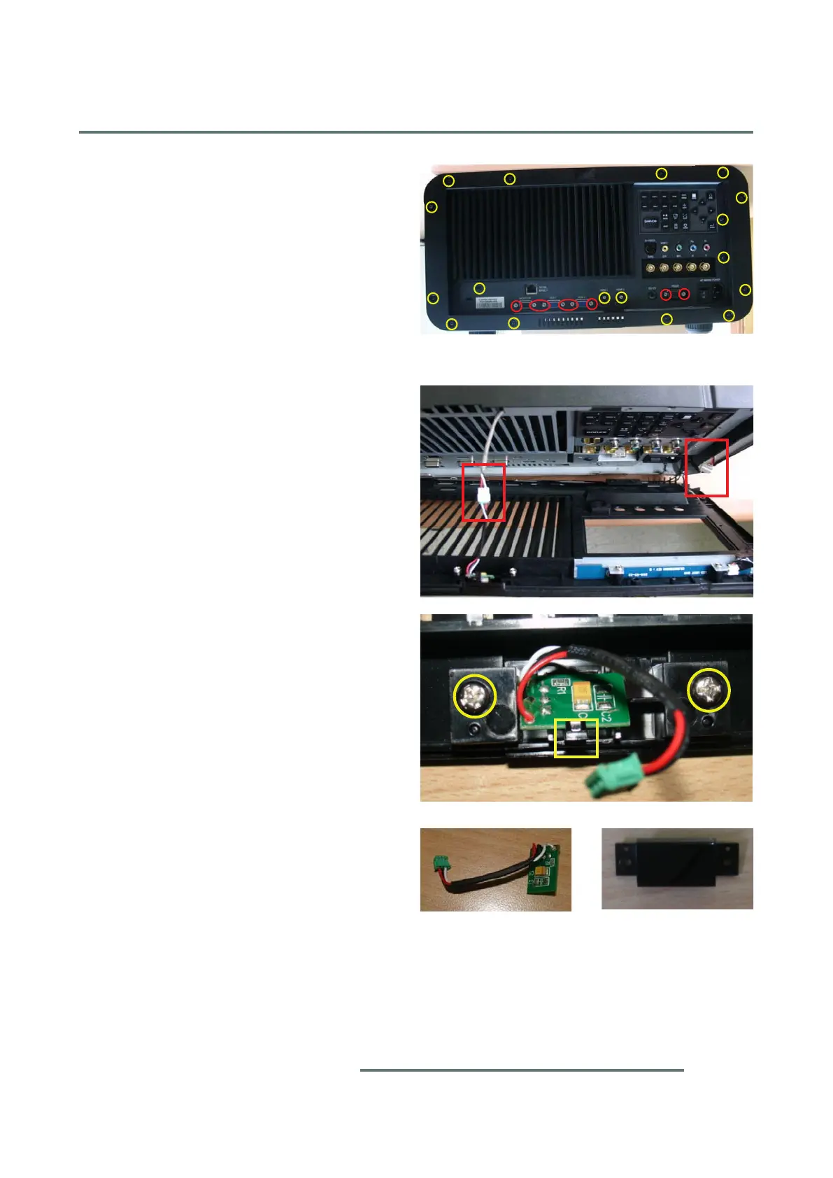
IR
IR Cover
 Loading...