4-6
CLM W6_CLM HD6 Jan 31, 2012
Chapter 4 Function Test & Alignment Procedure
4-7 PC MODE
Note: - When getting into function test, adjust the zoom and focus to
guarantee the image maximum and clearest, then start to test.
- Test signal: analog 1920 x 1080 @60Hz (for CLM HD6);
analog 1280 x 800 @60Hz (for CLM W6).
- We take CLM HD6 for example here.
- Connect VGA IN port of Projector with VGA port of Chroma and
connect VGA Out port of Projector with VGA port of Monitor by
VGA cable, check if the Projected image and the LCD image are
the same.
*Note: - VGA1 and VGA2 ports of Projector both need to do the
function test.
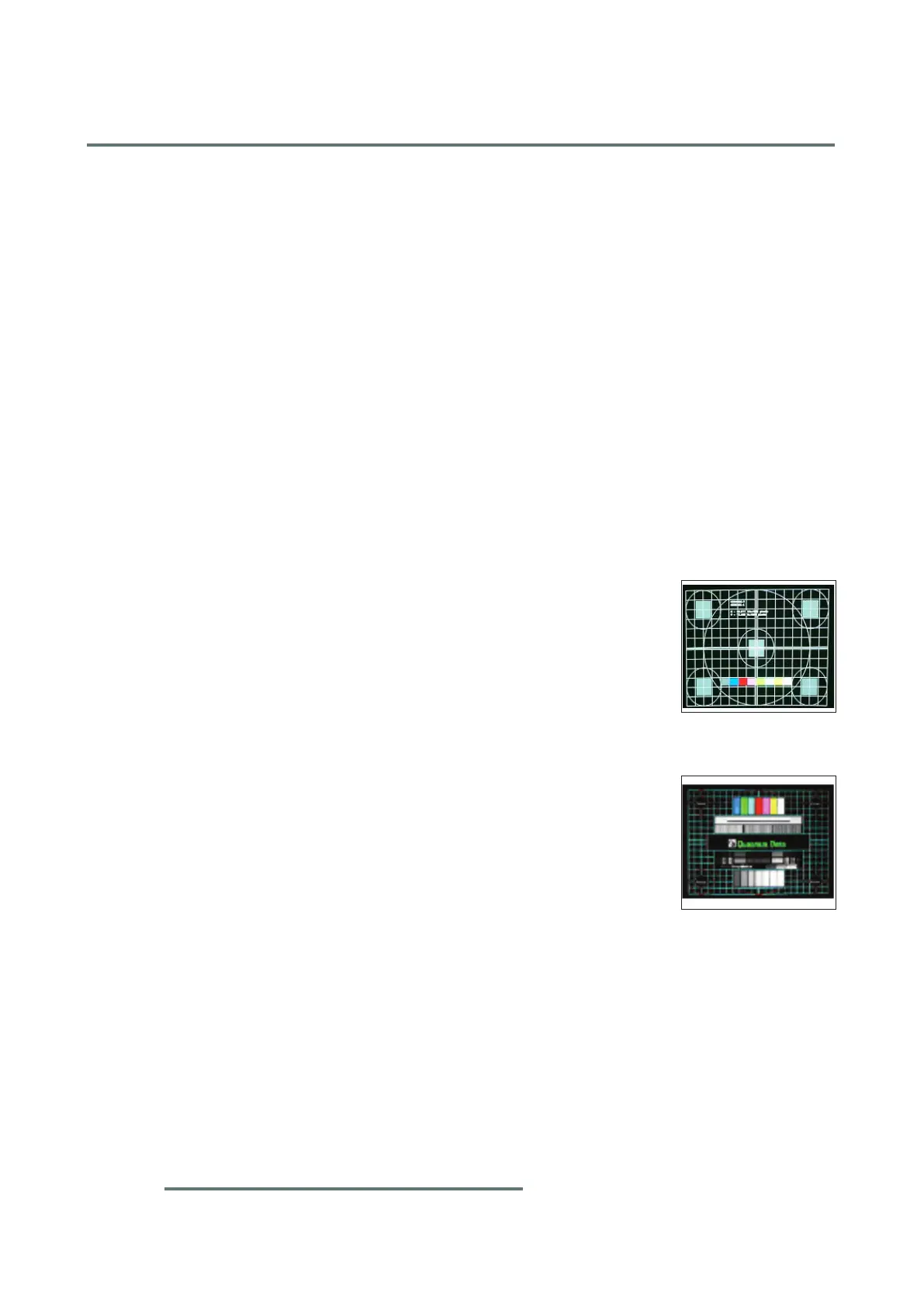
1. Frequency and Tracking Boundary
Procedure - Test equipment: video generator
- Test signal: analog 1920 x 1080 @60Hz
- Test Pattern: General-1 or Master
- Check and see if the image sharpness is well per-
formed.
- If not, re-adjust by the following steps:
(1) Select "Frequency" function to adjust the total
pixel number of pixel clock in one line period.
(2) Select "Tracking" function and use right or left
arrow key to adjust the value to minimize video
icker.
- Adjust Resync or Frequency/Tracking/H. Position/
V. Position to the inner screen.
Inspection item - Eliminate visual wavy noise by Resync,
Frequency or Tracking selection.
- Check if there is noise on the screen.
- Horizontal and vertical position of the video should
be adjustable to the screen frame.
Criteria - If there is noise on the screen, the product is con-
sidered as failure product.
- If there is noise on the screen, please pressplease press
"Menu" button to select "image" --> "Timings" -->
"H phase" for adjusting phase..
General-1
Master
 Loading...