Chapter 2 Disassembly Process
2-21
CLM W6_CLM HD6 Jan 31, 2012
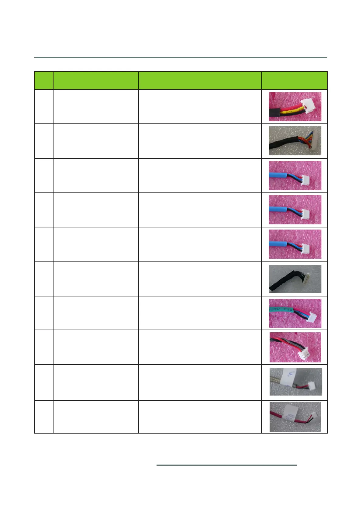
Item
Male Connector
on Connector Board
The key feature Figure
11 FAN-7 (120X25-R)
Composed of Red/Yellow/Black Wire,
White Connector and Black wire tube
(3 pin)
12 LED STATUS
Composed of Blue/Black/Yellow/Or-
ange/Red Wire, White Connector and
Black wire tube (10 pin)
13 F-FAN 11
Composed of Red/Blue/Black Wire,
White Connector and Blue wire tube
(3 pin)
14 F-FAN 10
Composed of Red/Blue/Black Wire,
White Connector and Blue wire tube
(3 pin)
15 F-FAN 13
Composed of Red/Blue/Black Wire,
White Connector and Blue wire tube
(3 pin)
16
Composed of Black Wire, White Con-
nector and Black wire tube (30 pin)
17 FAN-1(10532)
Composed of Red/Blue/Black Wire,
White Connector and Green wire tube
(3 pin)
18 FAN-2(70X20)
Composed of Red/Gray/Black Wire,
White Connector (3 pin)
19 FAN-3(50X20)
Composed of Red/Gray/Black Wire,
White Connector and Gray wire tube
(3 pin)
20
Composed of Red/White/Black Wire,
White Connector and Red wire tube
(3 pin)
 Loading...