Chapter 2 Disassembly Process
2-20
CLM W6_CLM HD6 Jan 31, 2012
Item
Male Connector
on Connector Board
The key feature Figure
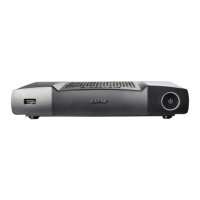
1 CNNT BD TO MB
Composed of Red/Black/Blue/Green/
Yellow/White Wire, Gray Connector
and Black wire tube
(60 pin)
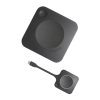
2 MOTOR-BD
Composed of Red/Black/Yellow/White
Wire, White Connector and Black wire
tube (4 pin)
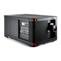
3 LENS SHIFT MOTOR-H
Composed of Yellow/Black/Brown/Red
Wire, White Connector and Blue wire
tube (4 pin)
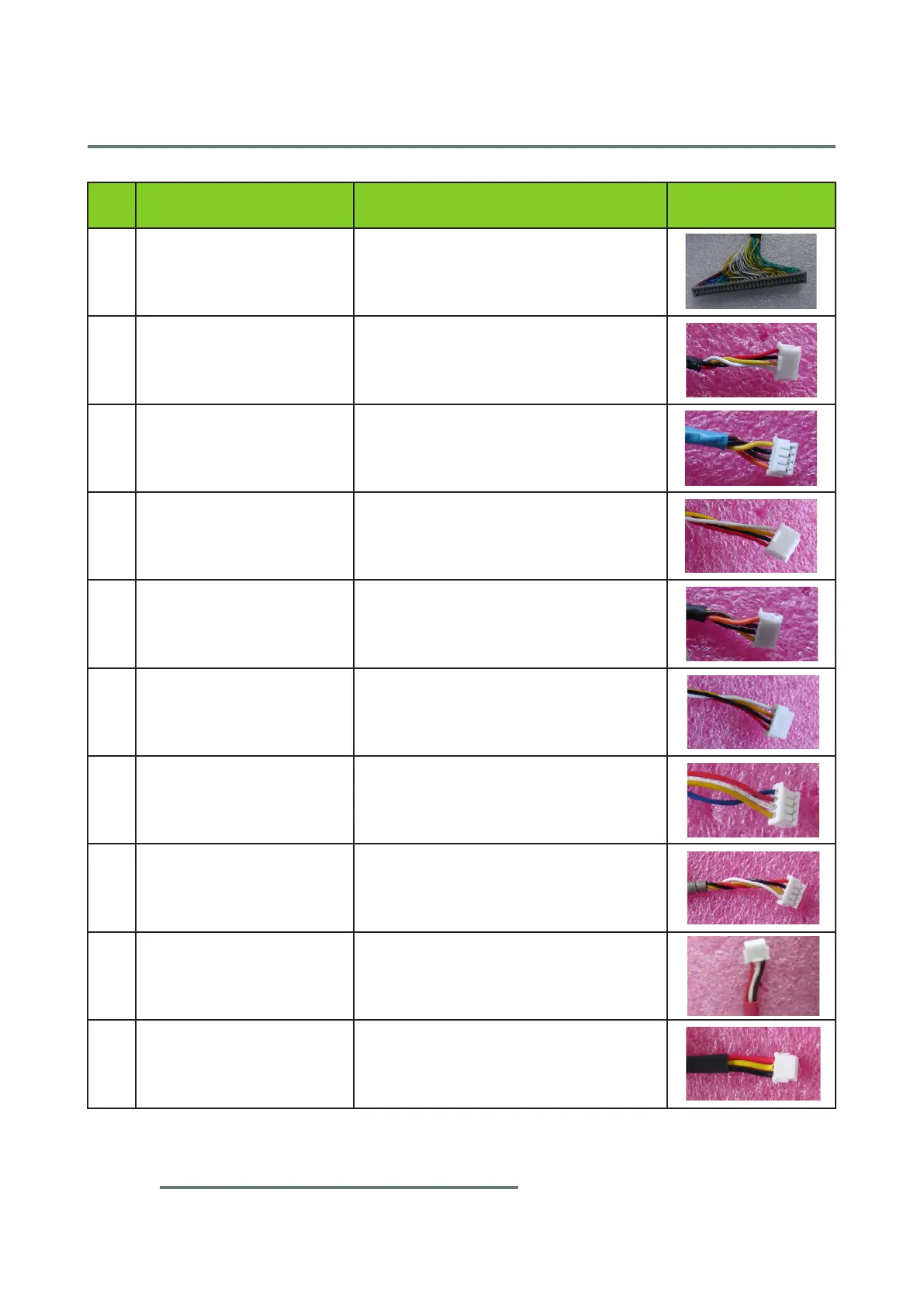
4 LENS SHIFT SENSOR-H
Composed of White/Yellow/Black/Red
Wire, White Connector (4 pin)
5 LENS SHIFT MOTOR-V
Composed of Pink/Brown/Black/Yellow
Wire, White Connector and Black wire
tube (4 pin)
6 LENS SHIFT SENSOR-V
Composed of White/Yellow/Black/Red
Wire, White Connector (4 pin)
7 PRISM-MOTOR
Composed of Yellow/White/Red/Blue
Wire, White Connector (4 pin)
8 PRISM-SENSOR
Composed of White/Yellow/Black/Red
Wire, White Connector and Brown
wire tube (4 pin)
9 FAN-5 (6025-R)
Composed of Red/White/Black Wire,
White Connector and Red wire tube
(3 pin)
10 FAN-6 (120X25-L)
Composed of Red/Yellow/Black Wire,
White Connector and Black wire tube
(3 pin)
 Loading...