11. Convergence
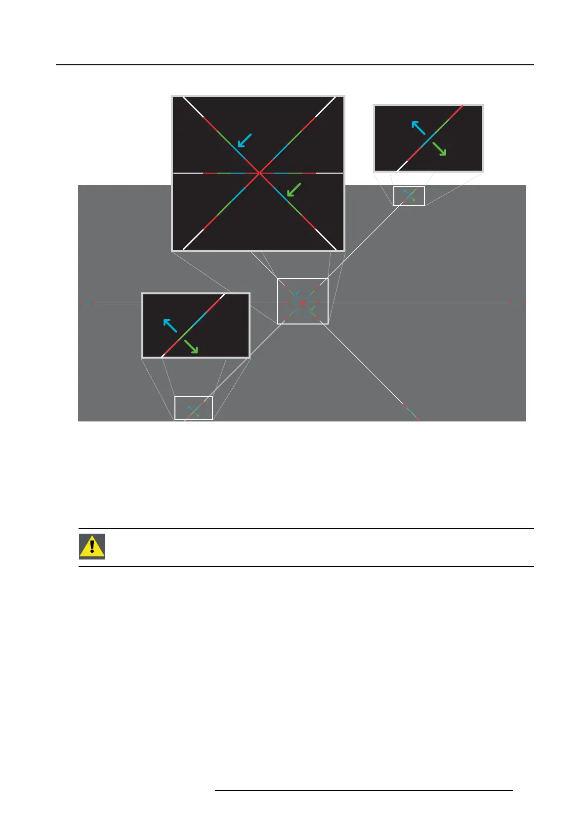
Convergence test pattern
4
1
2
5
3
6
3
6
2
5
4
1
Image 11-2
The test pattern illustrated above is specifical
ly designed for convergence purposes. The test pattern has three blue arrows num-
bered from 1 to 3 and three green arrows num bered from 4 to 6. The se number s an d colors correspond to those of the control
knobs. Eac h knob is marked with an arrow which corresponds to the direction indicated on the screen.
Adjustment Range
Prevent dam age to the system by limiting the amount/number of adjustment(s) made. Typically the convergence adjustments serve
to correct a convergence fault of a few pixels at the most. A ny convergence fault beyond this is c onsidered grossly abnormal and
likely indicates abuse or rough handling. However, in extreme cases correction of up to 10 pixels is possible.
CAUTION: The system does h ave an end of travel in either direction, bu t using excessive force m ay cause
damage. Please handle gently.
Troubleshooting ’dead zone’ of control knob
In the rare event that a knob is loose in the perfect convergence position, it is preferable to continue translating the image away for
approximately 20 to 30 pixels (max 1 revolution of the knob(s)). Note that this is the only time w e allow for extreme adjus tment.
Thereafter, return the image back immediately to the c orrect position. The knob should now have becom e tighter in the final position
and therefore resists turning due to vibrations and such. Repeat the procedure if you feel the knob is still loose.
R5906847 DP2K SLP SERIES 02/06/2017
107

 Loading...


