Installation and Disassembly 47
03/2016 CFPP Process Analyzer CFPP-4.2
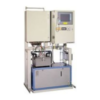
Fig. 7.1: Sample conditioning system (example)
2 Product inlet
3 Connections for coolant
4 Product outlet
• Adjust the sample conditioning system into an upright position.
• Secure the sample conditioning system at the fixing holes (1).
• Connect the coolant lines to the connections (3).
• Connect the product feed line to the product inlet (2).
• Connect the product outlet (4) to the analyzer.
• Connect the drain (5) to the drain.
The sample conditioning system is now installed and can be put into operation.
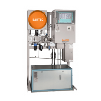
7.1.3 Securing the Analyzer
Adjust the analyzer vertically and horizontally and secure it to the floor with four fastening
screws M 12 (not included in delivery). For the dimensions of the fixing holes, please refer
to the supplied layout drawing.
1
1
2
4
5
3