EasyManua.ls Logo

BARTEC BENKE CFPP-4.2 - User Manual

BARTEC BENKE CFPP-4.2
107 pages
Print Icon
To Next Page IconTo Next Page
Loading...
CFPP Process Analyzer CFPP-4.2
Operating Instructions
395778MDHEN A
03/2016

Table of Contents

Questions and Answers

  • A
    Anne MitchellAug 7, 2025
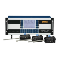
    What to do if BARTEC BENKE Measuring Instruments show implausible values?
    • C
      curtislopezAug 7, 2025
      If you're getting implausible values or the reproducibility of your measuring results decreases with your BARTEC BENKE Measuring Instruments, it could be due to several reasons. An alarm may have caused the measuring value output to reset to the initial value, so remove the cause of the alarm and carry out a reset. Check for errors in the sample conditioning system such as contamination, water, incorrect temperature, or gas in the product, and ensure the product is conditioned as specified in the technical data. Inspect the test filter for soiling and clean it if necessary. Also, verify the vacuum level at the vacuum pressure gauge and adjust it using the pressure controller if needed. Finally, a valve may be out of order, in which case you should replace the respective valve.
  • T
    Tina HarrisonAug 14, 2025
    Why BARTEC BENKE Measuring Instruments analyzer is off and overpressure control display is absent?
    • T
      Tiffany HudsonAug 14, 2025
      If your BARTEC BENKE Measuring Instruments analyzer is switched off or doesn't start and the display of overpressure control is not present, the issue might stem from an interrupted power supply, possibly due to a broken or blown fuse. Check and restore the power supply. Another potential cause is a faulty overpressure control system fusing, so remove the cause of the malfunction.
  • C
    Charles NelsonAug 22, 2025
    What to do if BARTEC BENKE Measuring Instruments analyzer won't start but overpressure control display is on?
    • N
      Nancy AdamsAug 22, 2025
      If your BARTEC BENKE Measuring Instruments analyzer is switched off or doesn't start, but the display of overpressure control is present, it could be due to several reasons: the overpressure control system may have switched off the analyzer or cannot start it; internal fuses might be faulty or blown; the power supply to the I/O board could be interrupted, or the I/O board itself may be faulty; or the instrument air supply may be interrupted. In each case, remove the cause of the malfunction.
  • J
    Jessica Allen MDAug 29, 2025
    Why BARTEC BENKE Measuring Instruments show no Ready signal?
    • A
      austinlarryAug 29, 2025
      If you're not getting a 'Ready' signal or a measuring result over a longer period of time with your BARTEC BENKE Measuring Instruments, it could be because the analyzer is switched off. Additionally, the PACS might be in “Standby” or “Shutdown” state, or not operating at all. Unsuitable parameter settings could also be the cause. Another reason may be the interrupted cable connection to the analyzer; in this case, remove the cause of the malfunction.
  • D
    Doston NormuminovJun 13, 2025
    Calibration/validation procedure

    Summary

    1 General

    1.1 About this Document

    Explains the purpose, intended audience, and scope of the operating instructions.

    1.2 Liability and Warranty

    Details BARTEC BENKE's liability and warranty terms for the analyzer.

    2 Safety

    2.1 General

    Provides general safety guidelines and emphasizes reading instructions before use.

    2.2 Intended Use

    Specifies the analyzer's intended purpose, operating environment, and product compatibility.

    2.3 Safety Symbols and Signal Words

    Defines signal words (DANGER, WARNING, CAUTION) and safety symbols used in the manual.

    2.4 Explosion Protection

    Details explosion protection measures, labeling, and types of protection for hazardous areas.

    2.4.1 Labeling on the Analyzer

    Explains the ATEX and NEC/CEC labeling on the analyzer for explosion protection.

    2.4.2 Types of Protection and certificates

    Describes different types of protection (e.g., 'p', 'd', 'e', 'm', 'i') used in the analyzer.

    2.4.3 Ensuring and Maintaining Explosion Protection

    Provides guidelines for ensuring and maintaining the analyzer's explosion protection.

    2.5 Protective Devices

    Lists and describes the various protective devices incorporated into the analyzer.

    2.6 Personnel

    Specifies qualifications and training requirements for personnel working with the analyzer.

    2.7 Personal Protective Equipment

    Outlines the required personal protective equipment (PPE) for working with the analyzer.

    2.8 Potential Dangers and Risks

    Highlights potential dangers and risks associated with the analyzer's operation.

    2.9 In Case of an Accident or Emergency

    Provides instructions on how to respond to accidents or emergencies involving the analyzer.

    3 Introduction

    3.1 The CFPP Process Analyzer CFPP-4.2

    Introduces the CFPP Process Analyzer CFPP-4.2, its purpose, and measurement capabilities.

    3.2 Significance of the Cold Filter Plugging Point

    Explains the importance of the Cold Filter Plugging Point (CFPP) for product behavior.

    3.3 Measuring Principle

    Describes the fundamental principle and process used by the analyzer for CFPP measurement.

    4 Technical Data

    5 Analyzer Description

    5.1 Overview and Operating Elements

    Provides an overview of the analyzer's components and user interface elements.

    5.2 Type plates

    Details the information found on the analyzer's various type plates and their significance.

    5.3 Analyzer Components

    Describes the main components housed within the analyzer's enclosures.

    5.3.1 Measuring unit enclosure

    Details the components and layout within the measuring unit enclosure.

    5.3.2 Measuring cell

    Describes the measuring cell, its sensors, and its function in the analysis process.

    5.4 Control box

    Explains the function and contents of the analyzer's control box.

    5.5 Sample conditioning system (optional)

    Describes the optional sample conditioning system and its components.

    5.6 Further Options

    Details optional features and configurations available for the analyzer.

    6 Transport, Packaging and Storage

    6.1 Transport

    Provides guidelines and warnings for safely transporting the analyzer.

    6.2 Delivery

    Instructions for checking the delivered analyzer for completeness and damage.

    6.3 Intermediate Storage

    Specifies conditions and requirements for storing the analyzer before installation.

    6.4 Packaging

    Information on the analyzer's packaging and its proper disposal.

    7 Installation and Disassembly

    7.1 Installation

    Covers the procedures and requirements for installing the analyzer.

    7.1.1 Operating Area Requirements

    Details the necessary environmental and space requirements for the installation site.

    7.1.2 Assembly of the Sample Conditioning System (Optional)

    Step-by-step guide for assembling the optional sample conditioning system.

    7.1.3 Securing the Analyzer

    Instructions on how to vertically and horizontally secure the analyzer to the floor.

    7.1.4 Tubing Connections

    Details the procedures and safety precautions for making tubing connections.

    7.1.5 Electrical Connections

    Provides instructions and safety warnings for making electrical connections.

    7.2 Disassembly

    Outlines the steps for safely disassembling the analyzer.

    7.2.1 Disconnecting Electrical Connections

    Details the procedure for safely disconnecting the analyzer's electrical connections.

    7.2.2 Removing Tubing Connections

    Provides instructions for safely disconnecting the analyzer's tubing connections.

    7.3 Disposal

    Guidance on the environmentally sound recycling and disposal of the analyzer.

    8 Initial Operation

    8.1 Putting the Analyzer into Operation

    Step-by-step guide for putting the analyzer into operation for the first time.

    8.2 Flushing the Product Feed Line

    Instructions for flushing the product feed line to remove contaminants before initial use.

    8.3 Initial Operation of the Sample Conditioning System (Optional)

    Procedures for the initial operation of the optional sample conditioning system.

    8.4 Feeding In Product

    Details on how to supply product to the analyzer for operation.

    8.5 Connecting the Analyzer to Instrument Air Supply

    Instructions for connecting the analyzer to the required instrument air supply.

    9 Operation

    9.1 Switching on the Analyzer

    Step-by-step guide on how to switch on the analyzer.

    9.2 Operation

    Describes the normal, automated operation of the analyzer.

    9.3 Switching off the Analyzer

    Details how to switch off the analyzer in normal and emergency situations.

    9.3.1 Switching off in Normal Operation

    Procedure for safely shutting down the analyzer during normal operation.

    9.3.2 Switching off in an Emergency

    Instructions for rapidly switching off the analyzer in an emergency.

    10 Maintenance

    10.1 Safety during Maintenance

    Highlights safety precautions and warnings to be observed during maintenance.

    10.1.1 Qualification of Personnel

    Specifies the required qualifications for personnel performing maintenance tasks.

    10.2 Measures after Maintenance

    Lists checks to be performed after completing maintenance work.

    10.3 Maintenance and Inspection Plan

    Provides a schedule and overview of required inspection and maintenance tasks.

    10.4 Checking the Protective Devices

    Details how to check the status and functionality of the analyzer's protective devices.

    10.5 General Visual Inspection

    Describes general visual checks to be performed on the analyzer.

    10.6 Visual Inspection Inside Measuring unit enclosure

    Guides visual inspection of components inside the measuring unit enclosure.

    10.7 Checking the residual-current device (RCD)

    Procedure for checking the functionality of the residual-current device (RCD).

    10.7.1 Measures after the RCD has triggered

    Steps to take after the residual-current device (RCD) has been triggered.

    10.7.2 Measures in case of troubles

    Actions to take if the RCD malfunctions or triggers unexpectedly.

    10.8 Checking the Test Filter

    Instructions for checking the cleanliness and flushing of the test filter.

    10.9 Cleaning the touchscreen

    Procedure for safely cleaning the analyzer's touchscreen.

    10.10 Changing the battery of the box PC

    Details on how to change the battery for the internal box PC.

    10.11 Checking for product and emptying vacuum tank

    Procedure for checking the vacuum tank and emptying it if necessary.

    10.12 Removing the Measuring Cell

    Instructions for safely removing the measuring cell for cleaning or other tasks.

    10.13 Cleaning the Test Filter

    Step-by-step guide for cleaning the test filter.

    10.14 Checking Liquid Level in the Sample Container

    Procedure for checking the liquid level in the sample container.

    10.14.1 Checking the Liquid Level in the Sample Container

    Detailed steps for checking the liquid level in the sample container.

    10.14.2 Adjusting the Liquid Level in the Sample Container

    Instructions on how to adjust the liquid level in the sample container.

    10.15 Reinstalling the Measuring Cell

    Procedure for correctly reinstalling the measuring cell.

    10.16 Remove the cover of the measuring cell housing

    Instructions for removing the cover of the measuring cell housing.

    10.17 Install the cover on the measuring cell housing

    Procedure for installing the cover back onto the measuring cell housing.

    11 Troubleshooting

    BARTEC BENKE CFPP-4.2 Specifications

    General IconGeneral
    BrandBARTEC BENKE
    ModelCFPP-4.2
    CategoryMeasuring Instruments
    LanguageEnglish

    Related product manuals