32 Analyzer Description
CFPP Process Analyzer CFPP-4.2 03/2016
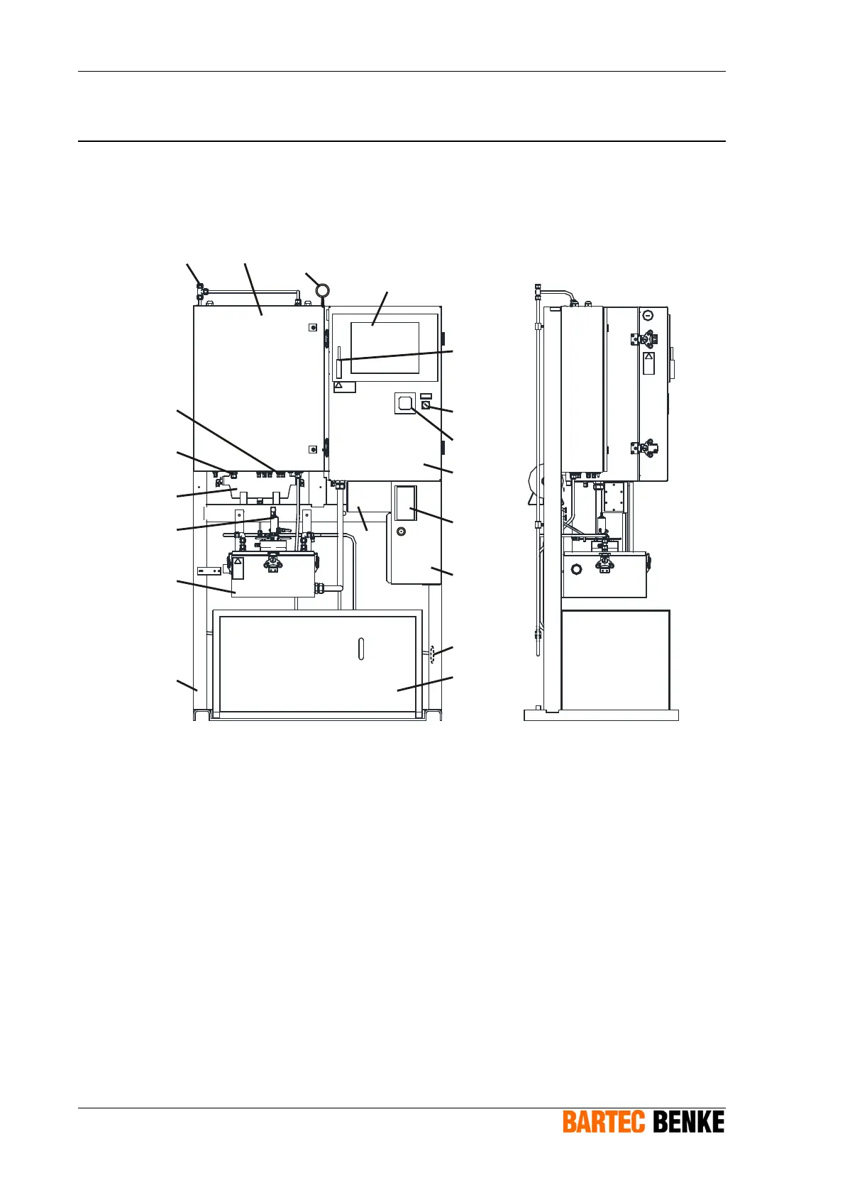
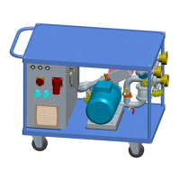
5.1 Overview and Operating Elements
The following illustration gives you an overview of the analyzer:
1
2
3
4
5
7
8
9
11
10
12
18
14
15
16
17
13
6
19
Fig. 5.1: Overview
1 Vent connection (waste gas outlet)
2 Measuring unit enclosure
3 Transport eye
4 Touchscreen
5 Pen
6 Key switch
7 Overpressure control display
8 Control box (Ex p)
9 Type plate
10 Signal junction box (Ex e)
11 Power supply box (Ex e)
12 Drain connection (waste liquid
outlet)
13 Chiller for Liquids
14 Frame
15 Measuring cell housing (Ex p)
16 Measuring cell
17 Vacuum tank
18 Instrument air connection
The measurement takes place inside the measuring cell (16). The Chiller for Liquids (13)
combined with a heat exchanger and peltier elements in the measuring cell housing (15)
cool the sample. The measuring cell housing is pressurized together with the control box
(8). The control box contains the analyzer control unit and the control unit for the cooling
system.