Do you have a question about the BARTEC BENKE HYGROPHIL F 5673 and is the answer not in the manual?
Explains the measurement principle, function, and applications of the HYGROPHIL® F 5673 hygrometer.
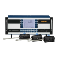
Details the operator controls and display elements on the front of the evaluation unit.
Explains the functions of various keys like VOL%, PPM, DT, FP, MC, VP, CH1-3, TT, SP, WL, F1, F2, HELP, PROG.
Provides detailed technical specifications for the Evaluation Unit F 5673.
Details electrical data, interfaces, electronics, and ambient conditions for the CPU plug-in unit.
Specifies electrical data and ambient conditions for the DC power supply plug-in unit.
Specifies electrical data and ambient conditions for the AC power supply plug-in unit.
Details electrical data, resolution, sampling, and ambient conditions for the Analog I/O Ex module.
Lists electrical data, analog output, RS485, RS232, Profibus, USB, and ambient conditions for the interface module.
Provides electrical data, relay specifications, and switching operations for the Relay-Interface module.
Details electrical data, connection type, interface, measuring range, resolution, and ambient conditions.
Describes the design, applications, temperature/pressure limits, accuracy, and approvals of the L166x sensor.
Emphasizes that casing opening is reserved strictly for qualified technical staff.
Details safe installation, operation in hazardous areas, and handling of sensors and cables.
General instructions before installing the evaluation unit, including voltage check and wiring.
Details the installation and wiring of the L166x sensor.
Provides step-by-step instructions for wiring the Pt 100 cable and the fibre optic cable.
Details the installation of the L166x sensor and available accessories.
Provides advice on installing the sensor, including protection cap and ferrule placement.
Instructions on connecting the evaluation unit to the mains and software initialization.
Explains the automatic sensor equalization process and how to trigger it manually.
Guides through setting up the history graphic display, including selecting parameters and time periods.
Details how to define the start and end date/time for presenting historical data.
Explains how to select a graph line and open the dialog for editing the graph presentation.
Instructions for connecting an external medium and copying the database via the USB port.
Explains how to enter the programming mode and the password entry procedure.
Indicates errors preventing measurement operation, with error signs and output signals.
Details the procedure for cleaning the moisture-sensitive layer of the L166x sensor.
Explains Modbus RTU mode, RS485/RS232 connection, and function codes.
Describes Profibus DP interface, data transfer, slave address, and data field structure.
Explains the measurement principle, function, and applications of the HYGROPHIL® F 5673 hygrometer.
Details the operator controls and display elements on the front of the evaluation unit.
Explains the functions of various keys like VOL%, PPM, DT, FP, MC, VP, CH1-3, TT, SP, WL, F1, F2, HELP, PROG.
Provides detailed technical specifications for the Evaluation Unit F 5673.
Details electrical data, interfaces, electronics, and ambient conditions for the CPU plug-in unit.
Specifies electrical data and ambient conditions for the DC power supply plug-in unit.
Specifies electrical data and ambient conditions for the AC power supply plug-in unit.
Details electrical data, resolution, sampling, and ambient conditions for the Analog I/O Ex module.
Lists electrical data, analog output, RS485, RS232, Profibus, USB, and ambient conditions for the interface module.
Provides electrical data, relay specifications, and switching operations for the Relay-Interface module.
Details electrical data, connection type, interface, measuring range, resolution, and ambient conditions.
Describes the design, applications, temperature/pressure limits, accuracy, and approvals of the L166x sensor.
Emphasizes that casing opening is reserved strictly for qualified technical staff.
Details safe installation, operation in hazardous areas, and handling of sensors and cables.
General instructions before installing the evaluation unit, including voltage check and wiring.
Details the installation and wiring of the L166x sensor.
Provides step-by-step instructions for wiring the Pt 100 cable and the fibre optic cable.
Details the installation of the L166x sensor and available accessories.
Provides advice on installing the sensor, including protection cap and ferrule placement.
Instructions on connecting the evaluation unit to the mains and software initialization.
Explains the automatic sensor equalization process and how to trigger it manually.
Guides through setting up the history graphic display, including selecting parameters and time periods.
Details how to define the start and end date/time for presenting historical data.
Explains how to select a graph line and open the dialog for editing the graph presentation.
Instructions for connecting an external medium and copying the database via the USB port.
Explains how to enter the programming mode and the password entry procedure.
Indicates errors preventing measurement operation, with error signs and output signals.
Details the procedure for cleaning the moisture-sensitive layer of the L166x sensor.
Explains Modbus RTU mode, RS485/RS232 connection, and function codes.
Describes Profibus DP interface, data transfer, slave address, and data field structure.
| Material | Stainless steel |
|---|---|
| Measured variable | Relative humidity, temperature |
| Operating temperature | -20 °C to +60 °C |
| Output signal | 4-20 mA, HART |
| Explosion protection | ATEX, IECEx |
| Measurement Range | 0 to 100 % RH |
| Connection | 1/2" NPT |
| Device Type | Hygrophil F |