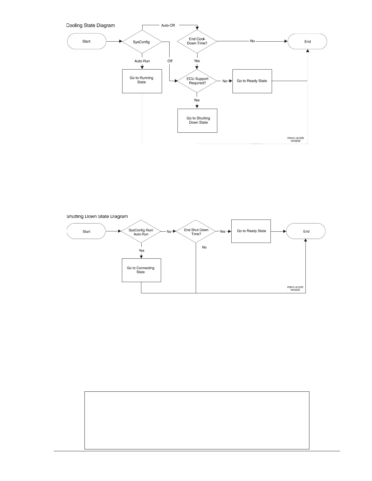
Figure 3-26. Cooling State Diagram
Shutting Down State
The Shutting Down State follows the sequence of events shown in Figure 3-27. If the Engine Shut Down
timer expires, the unit transitions to the Ready state. If system configuration changes back to Run/Auto-
Run, then this state will transition to the Connecting state, because if the unit is in a Shutting Down state,
it will continue to follow the ECU Power Support diagram.
Figure 3-27. Shutting Down State Diagram
Alarm State
All states except Reset can transition to the Alarm state. The State Machine frequently checks for alarms
and pre-alarms before running through each state. If an alarm is flagged in the initial alarm check, then
the unit goes into an Alarm state and waits there for the alarm to clear. If it is in Run/Auto-Run, then the
alarm can be cleared only by going to Off. When the alarm clears, the Alarm state will transition to the
Shutting Down state and then go to the Ready state. If ECU Support is enabled, the unit will go to the
Pulsing state immediately after transitioning to the Ready state. If in Off/Auto-Off, the alarm can be
cleared only if the alarm condition ceases or the user disables the alarm through BESTCOMS. Figure 3-
28 illustrates the Alarm State flowchart.
NOTE
With ECU Support enabled, if an alarm was tripped by an ECU value, then it will
not clear. This is because in the Alarm state, the fuel solenoid is open, causing
the ECU to not have power to update the internal variables. To clear an alarm in
this event, the user must remotely place the unit in Off mode through
BESTCOMS or go from Auto-Off to Off via the front panel HMI to force a pulse of
the ECU.
9355400990 Rev H DGC-500 Functional Description 3-35