Connection diagrams
Operation manual b maXX BM4100 (NWR)
Document no.: 5.04052.09 Baumüller Nürnberg GmbH
72
of 142
7.18
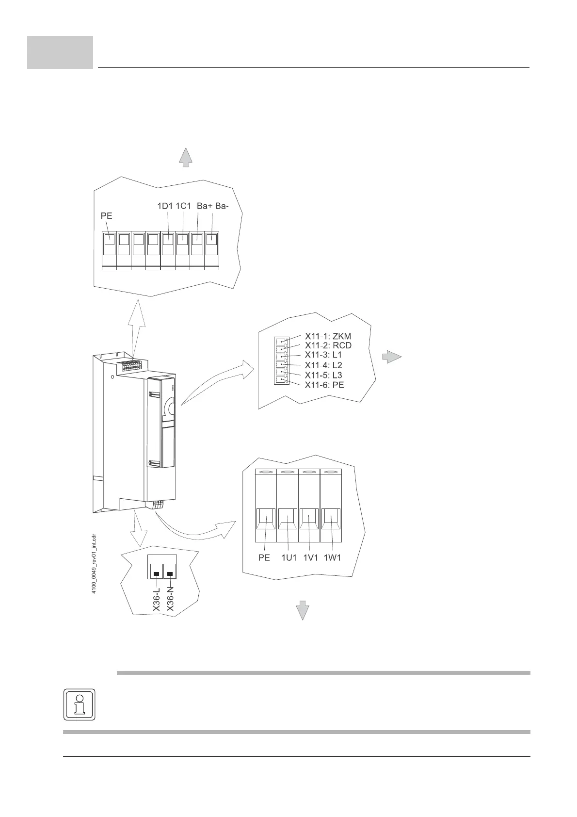
The electrical connections for device BM4145 are shown in the following figure:
Figure 30: Electrical connections for mains, DC-link, upon others for BM4145
at the back (back panel)
Fan at the back (back panel)
1D1, 1C1
DC-link
Ba+, Ba-
Chopper resistor
for discharge
in front (cover)
1U1, 1V1, 1W1
Mains connections
NOTE
X11-1 (ZKM) and X11-2 (RCD) must be short-circuited with a cable adapted for the mains
voltage.