Installation
Operation manual b maXX BM4100 (NWR)
Document no.: 5.04052.09
77
of 142
7
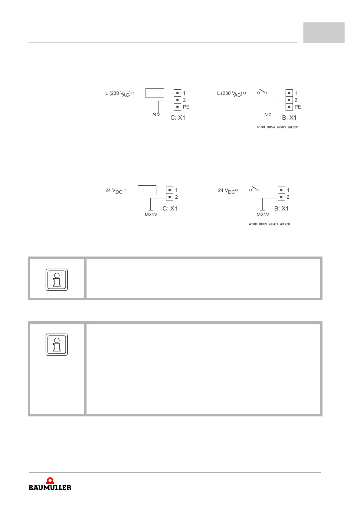
Main contactor control with SEA-01 and SRM-01
Coil main contactor Monitoring contact main contactor
Figure 35: Connection main contactor SEA-01 and SRM-01
Main contactor control with SEA-02 and SRM-02
Coil main contactor Monitoring contact main contactor
Figure 36: Connection main contactor SEA-02 and SRM-02
NOTE
The maximal switching current of SEA is 8 A.
NOTE
* in case you consider UL 508 C: limit the current to 4 A.
** do not provide the terminals X100-3 or X100-4 with voltage, if the device is not sup-
plied with voltage via X100-1/2.
(the signals "mains on" and "chopper resistor" are internal digital control signals of
the system
b maXX
®
. They are used at applications with DC link connection.)
*** The PSI module may not be attached or withdrawn, if the b maXX® device is
switched on. Beforehand switch off the device.
Further notes for the usage of the PSI module are to be found in parameter manual