Installation
Operation manual b maXX BM4100 (NWR)
Document no.: 5.04052.09
71
of 142
7
7.18 Connection diagrams
The figures from ZPage 71– to ZPage 73– show the connections for protective conduc-
tor, mains, chopper resistor, DC link. ZFigure 32– on page 74 shows the connection of
control voltage and the connections of the controller unit. ZFigure 34– on page 76 shows
the connections of the function modules in the slots A to D.
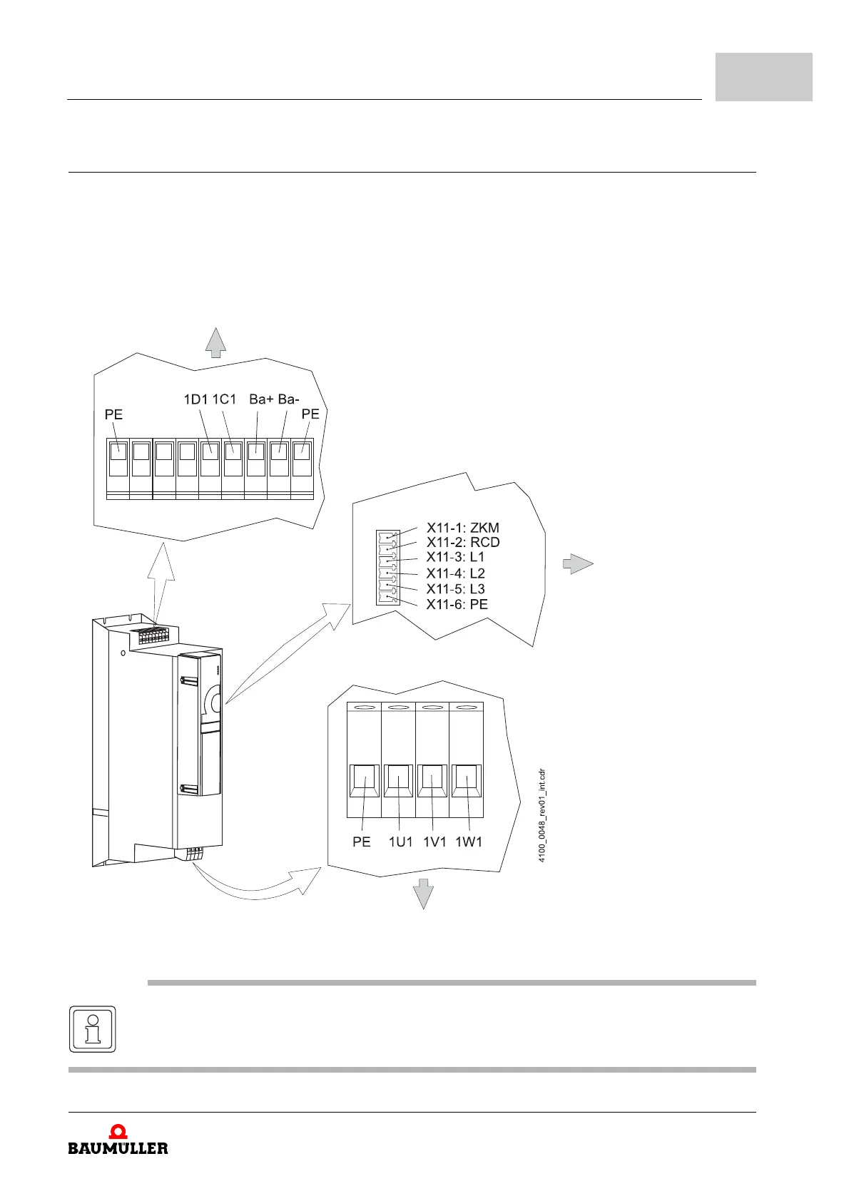
The electrical connections for the device BM4135 are shown in the following figure:
at the back (back panel)
at the back (back panel)
Figure 29: Electrical connections for mains, DC-link, upon others for BM4135
1D1, 1C1
DC-link
Ba+, Ba-
Chopper resistor
for discharge
in front (cover)
1U1, 1V1, 1W1
Mains connec-
tions
NOTE
X11-1 (ZKM) and X11-2 (RCD) must be short-circuited with a cable adapted for the mains
voltage.