Installing the BayStack 350 Switch
304376-B Rev 00
2-13
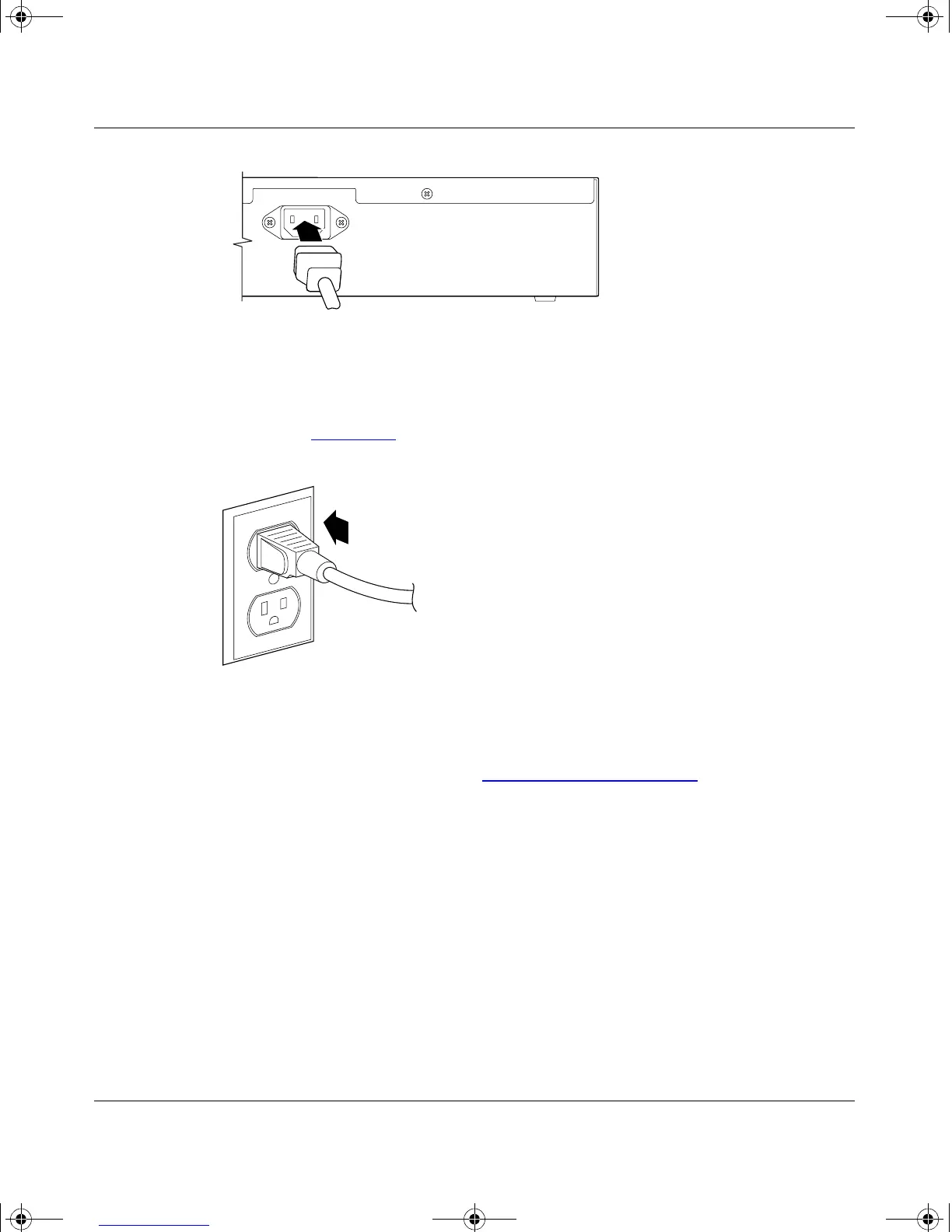
Figure 2-7. BayStack 350 Switch AC Power Receptacle
2.
Plug the other end of the AC power cord into the grounded AC power
outlet (Figure 2-8
).
Figure 2-8. Grounded AC Power Outlet
3.
Proceed to the next section, “Verifying the Installation,” to verify proper
operation.
Verifying the Installation
When power is applied to the switch, power-on self-tests are run.
You can verify proper operation of the BayStack 350 switch by observing the
front-panel LEDs or by viewing the self-test results as displayed in the BayStack
350 switch Self-Test screen.
100-240V
47-63Hz~
BS35039A
612FA
kombk.book Page 13 Thursday, February 18, 1999 10:59 AM