3 Disassembly / Assembly
Infusomat® compact
plus
P 1.0 3 - 17
EN
For internal use, only
3.10 PROCESSOR BOARD Designation Ord. No.
Processor board ICP . . . . . . . . . . . . . . . . . . . . . . . . . . . . . .34522201
Disassembly
✓ Unit has been opened.
✓ Loudspeaker connector (Fig. 3 - 21 / Item 5) has been discon-
nected from the processor board.
✓ Data of the pump are backed up before the processor board is
replaced (see "compact
plus
Service Tool" Instructions for Use).
1. Unlock and disconnect the connector of the accessory con-
nector cable on the processor board (Fig. 3 - 21 / Item 2) .
2. Completely unlock the connector for the connecting cable of
the display board
(Fig. 3 - 21 / Item 3) and pull out the ribbon
cable.
3. Unscrew the four screws (Fig. 3 - 21 / Item 1) using a 10IP
TORX plus screwdriver and remove the processor board
(Fig. 3 - 21 / Item 4).
Assembly
✓ Accessory connector is mounted.
1. Establish all cable connections.
2. Tighten the screws with a torque of 0.7 Nm ± 0.07 Nm (first
and second screwing).
If the processor board ICP has been replaced, the serial number of
the device must be re-entered via the compact
plus
Service Tool, and
the device must be recalibrated.
When the check after repair was passed, the device must be reset
to factory settings using the compact
plus
Service Tool. Otherwise,
the message "Do not use the device on patient." will be displayed
after switching on the device.
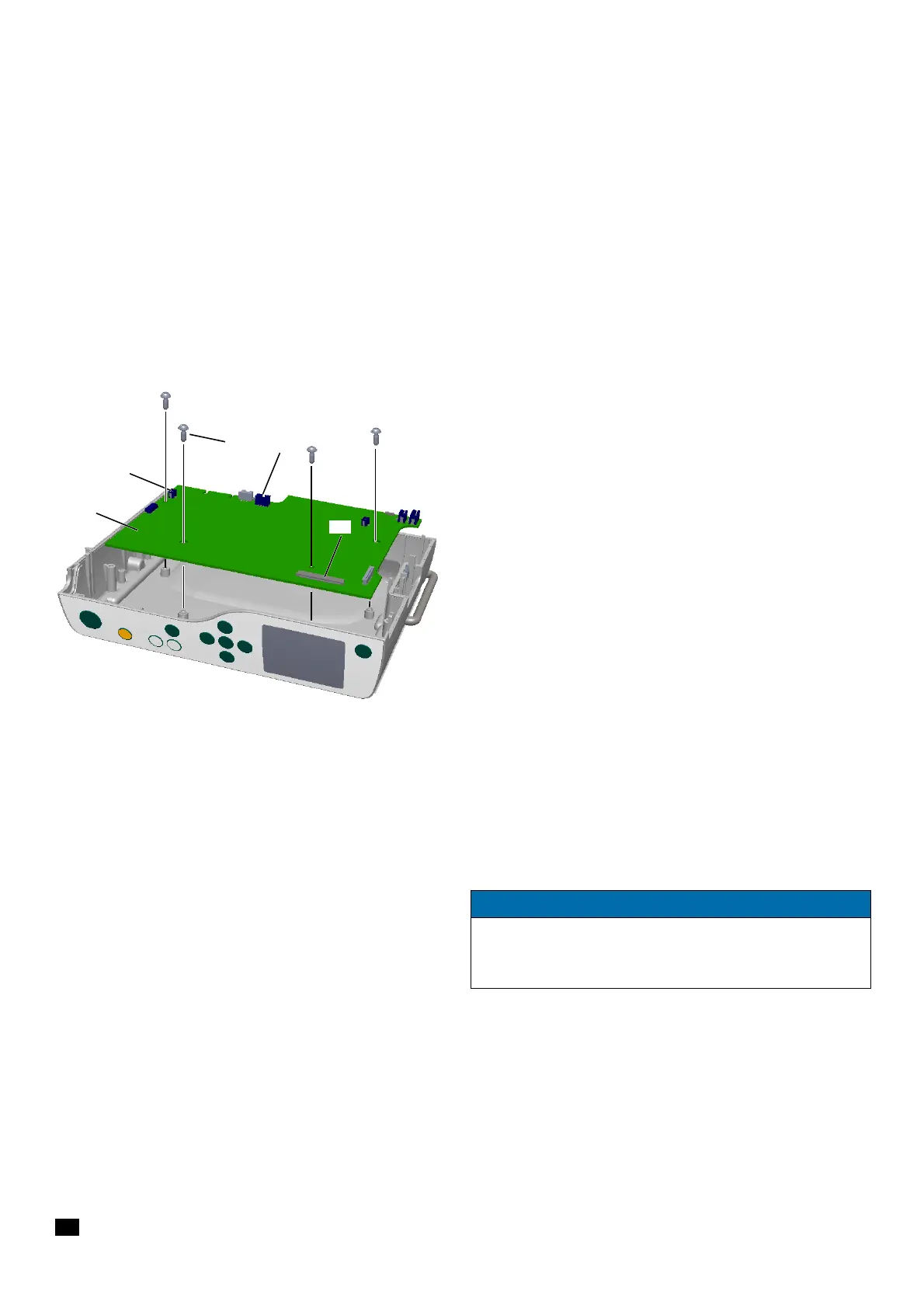
Fig. 3 - 21
1 Screw DELTA PT 30x8 WN 5451
2 Connector accessory cable
3 Connector display board
4 Processor board
5 Connector loudspeaker
NOTICE
When a new processor board ICP has been installed, the data
backed up on PC must be imported back into the unit.
(see "compact
plus
Service Tool" Instructions for Use)