Integrated safety
EL72x1-901x 181Version: 1.9
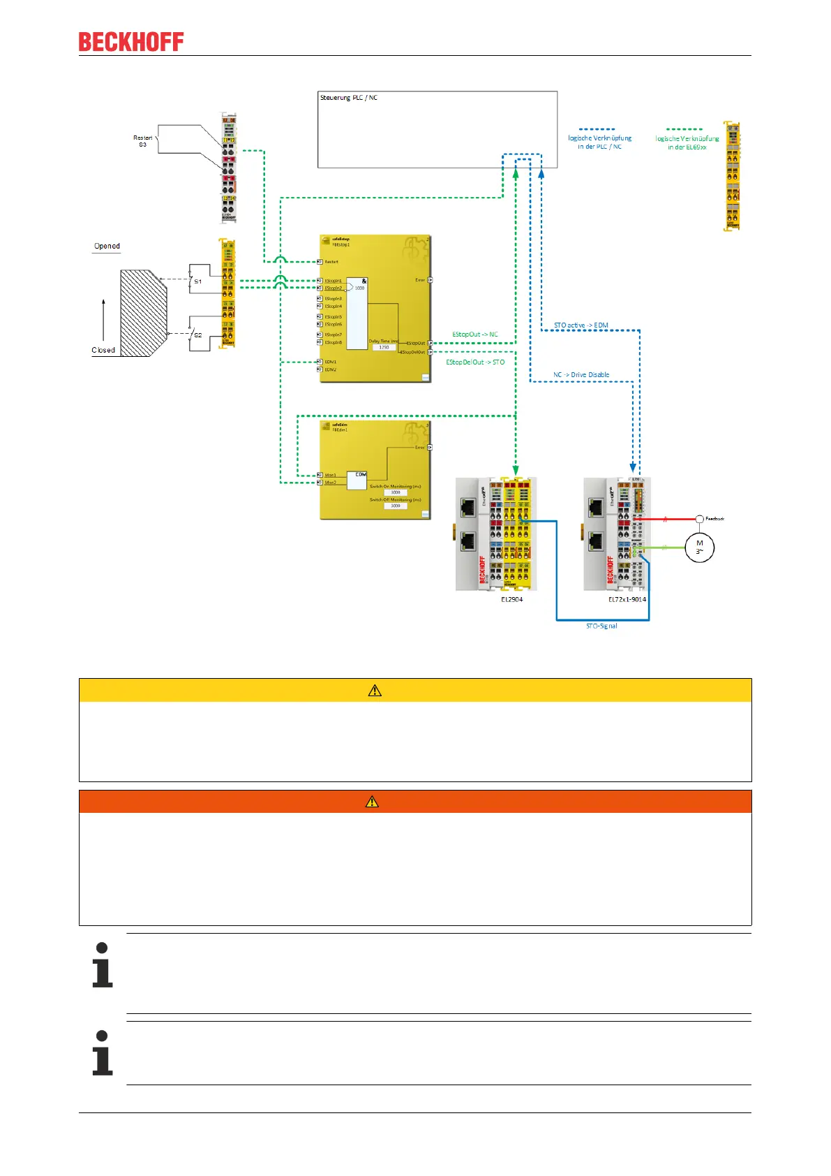
Fig.214: Connection example for EL72x1_9014 with STO
CAUTION
Implement a restart lock in the machine!
The restart lock is NOT part of the safety chain and must be implemented in the machine!
If the risk analysis returns the result that a restart is to be realized in the safety controller, then the restart
must also be placed on a safe input.
WARNING
Wiring only inside the control cabinet
The wiring between the EL2904 and the STO input of the EL72x1-9014 must be located in the same control
cabinet in order to be able to assume a fault exclusion for the cross-circuit or external power supply of the
wiring between EL2904 and EL72x1-9014.
The evaluation of this wiring and the evaluation of whether the fault exclusion is permissible must be done
by the machine manufacturer or user.
Calculation EL72x1-9014
The EL72x1-9014 is not taken into account in the calculation of the Performance Level DIN EN ISO
13849-1 since it behaves non-reactively to the safety function. The PFH value goes into the calcula-
tion according to EN 62061 with a value of 0.
Operation of several EL72x1-9014 terminals at the same time
A maximum of 10 STO inputs of the corresponding EL72x1-9014 can be operated at the same time
with a cut-off channel of the EL2904.

 Loading...


