Table of figures
EL72x1-901x258 Version: 1.9
Table of figures
Fig. 1 EL5021 EL terminal, standard IP20 IO device with serial/ batch number and revision ID (since
2014/01)....................................................................................................................................... 12
Fig. 2 EK1100 EtherCAT coupler, standard IP20 IO device with serial/ batch number......................... 12
Fig. 3 CU2016 switch with serial/ batch number.................................................................................... 12
Fig. 4 EL3202-0020 with serial/ batch number 26131006 and unique ID-number 204418 ................... 13
Fig. 5 EP1258-00001 IP67 EtherCAT Box with batch number/ date code 22090101 and unique se-
rial number 158102...................................................................................................................... 13
Fig. 6 EP1908-0002 IP67 EtherCAT Safety Box with batch number/ date code 071201FF and
unique serial number 00346070 .................................................................................................. 13
Fig. 7 EL2904 IP20 safety terminal with batch number/ date code 50110302 and unique serial num-
ber 00331701............................................................................................................................... 13
Fig. 8 ELM3604-0002 terminal with unique ID number (QR code) 100001051 and serial/ batch num-
ber 44160201............................................................................................................................... 14
Fig. 9 BIC as data matrix code (DMC, code scheme ECC200)............................................................. 15
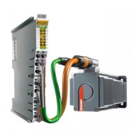
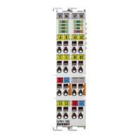
Fig. 10 EL7201-901x ............................................................................................................................... 17
Fig. 11 EL7211-901x, EL7221-901x........................................................................................................ 18
Fig. 12 Three synchronous motor coils, each offset by 120°................................................................... 22
Fig. 13 Limitation to the rated motor current ........................................................................................... 24
Fig. 14 System manager current calculation .......................................................................................... 26
Fig. 15 EtherCAT tab -> Advanced Settings -> Behavior -> Watchdog .................................................. 27
Fig. 16 States of the EtherCAT State Machine........................................................................................ 29
Fig. 17 "CoE Online " tab......................................................................................................................... 31
Fig. 18 Startup list in the TwinCAT System Manager ............................................................................. 32
Fig. 19 Offline list ..................................................................................................................................... 33
Fig. 20 Online list .................................................................................................................................... 33
Fig. 21 Spring contacts of the Beckhoff I/O components......................................................................... 37
Fig. 22 Attaching on mounting rail ........................................................................................................... 38
Fig. 23 Disassembling of terminal............................................................................................................ 39
Fig. 24 Power contact on left side............................................................................................................ 40
Fig. 25 Recommended distances of installation position for operating without fan ................................. 41
Fig. 26 Recommended distances for installation position for operation with fan..................................... 42
Fig. 27 Other installation positions, example 1........................................................................................ 42
Fig. 28 Other installation positions, example 2........................................................................................ 43
Fig. 29 Correct positioning....................................................................................................................... 43
Fig. 30 Incorrect positioning..................................................................................................................... 44
Fig. 31 Standard wiring............................................................................................................................ 45
Fig. 32 Pluggable wiring .......................................................................................................................... 45
Fig. 33 High Density Terminals................................................................................................................ 46
Fig. 34 Connecting a cable on a terminal point ....................................................................................... 47
Fig. 35 Example configuration for temperature measurement................................................................. 48
Fig. 36 Shield busbar............................................................................................................................... 49
Fig. 37 Shield busbar clamp .................................................................................................................... 49
Fig. 38 Shield connection ........................................................................................................................ 50
Fig. 39 Note ............................................................................................................................................. 52
Fig. 40 EL7201-901x - LEDs ................................................................................................................... 53
Fig. 41 EL7201-901x Connection ............................................................................................................ 54

 Loading...
