Commissioning
EL72x1-901x 145Version: 1.9
Index (hex) Name Meaning
MDP 407 Profile DS402 Profile
8010:12 [}190] 2002:12 [}212]
Current loop integral time is calculated according to the symmetrical optimum
8010:13 [}190] 2002:13 [}212]
Current loop proportional gain is calculated according to the symmetrical optimum
8011:11 [}193] 2003:11 [}215]
Max. current is adopted directly from the electronic type plate of the
connected motor
8011:12 [}193] 2003:12 [}215]
Rated current is adopted directly from the electronic type plate of the
connected motor
8011:13 [}193] 2003:13 [}215]
Motor pole pairs is adopted directly from the electronic type plate of the
connected motor
8011:15 [}193] 2003:15 [}215]
Commutation offset is always set to -90°
8011:16 [}193] 2003:16 [}215]
Torque constant is adopted directly from the electronic type plate of the
connected motor
8011:18 [}193] 2003:18 [}215]
Rotor moment of inertia is adopted directly from the electronic type plate of the
connected motor
8011:19 [}193] 2003:19 [}215]
Winding inductance is adopted directly from the electronic type plate of the
connected motor
8011:1B [}193] 2003:1B [}215]
Motor speed limitation Calculation of the max. speed of the connected motor
8011:2B [}193] 2003:2B [}215]
Motor temperature warn level is adopted directly from the electronic type plate of the
connected motor
8011:2C [}193] 2003:2C [}215]
Motor temperature error level is adopted directly from the electronic type plate of the
connected motor
8011:2D [}193] 2003:2D [}215]
Motor thermal time constant is adopted directly from the electronic type plate of the
connected motor
8012:11 [}194] 2004:11 [}216]
Release delay is adopted directly from the electronic type plate of the
connected motor
8012:12 [}194] 2004:12 [}216]
Application delay is adopted directly from the electronic type plate of the
connected motor
8012:14 [}194] 2004:14 [}216]
Brake moment of inertia is adopted directly from the electronic type plate of the
connected motor
5.3.8 Configuring the limit switch
Software end position monitoring
The TwinCAT NC can be used to set software end position monitoring for the EL72x1-xxxx to ensure the
safety of the system. The axis does not move beyond the set position (maximum/minimum end position).
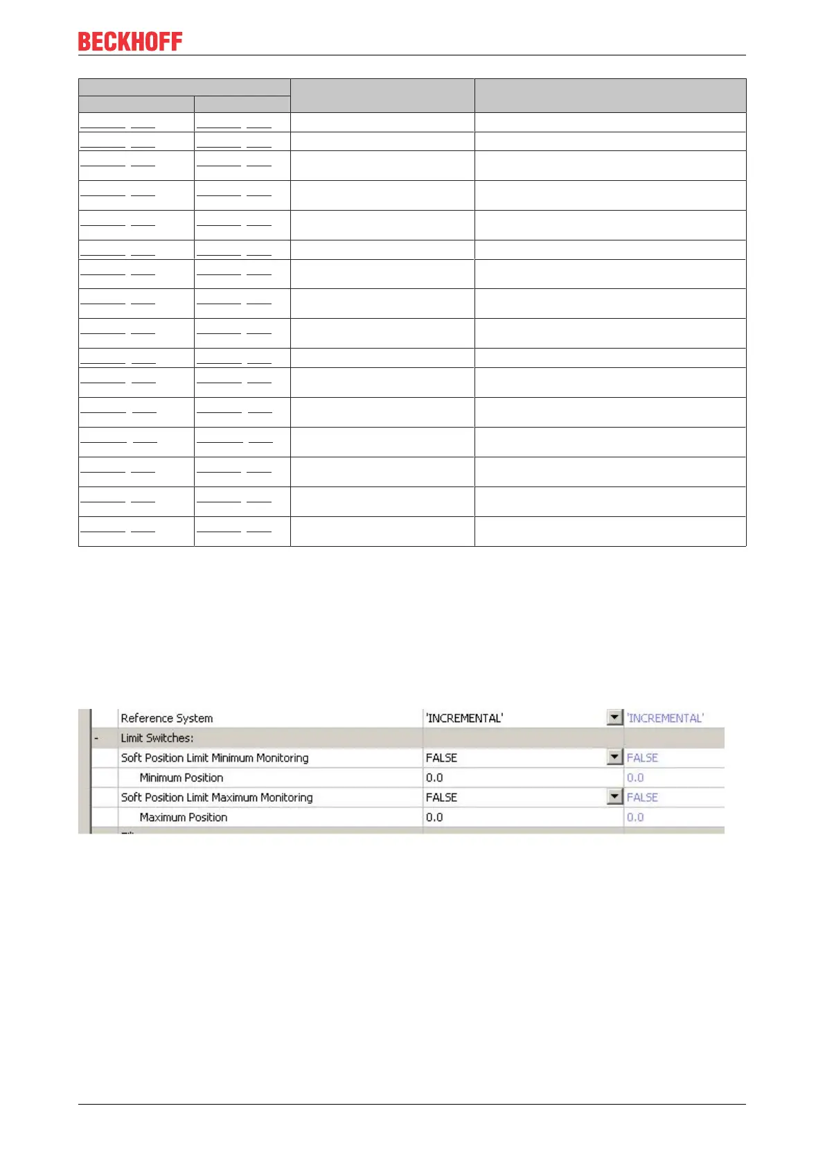
End position monitoring can be activated in the Parameter tab for the corresponding axis.
Fig.178: Pull-down menu for activating end position monitoring
Limit switch
It is not possible to connect a limit switch directly to the terminal for direct evaluation. Alternatively, the limit
switch can be read via a digital input terminal, or the software end position monitoring can be used.

 Loading...


