Installation
EL72x1-901x54 Version: 1.9
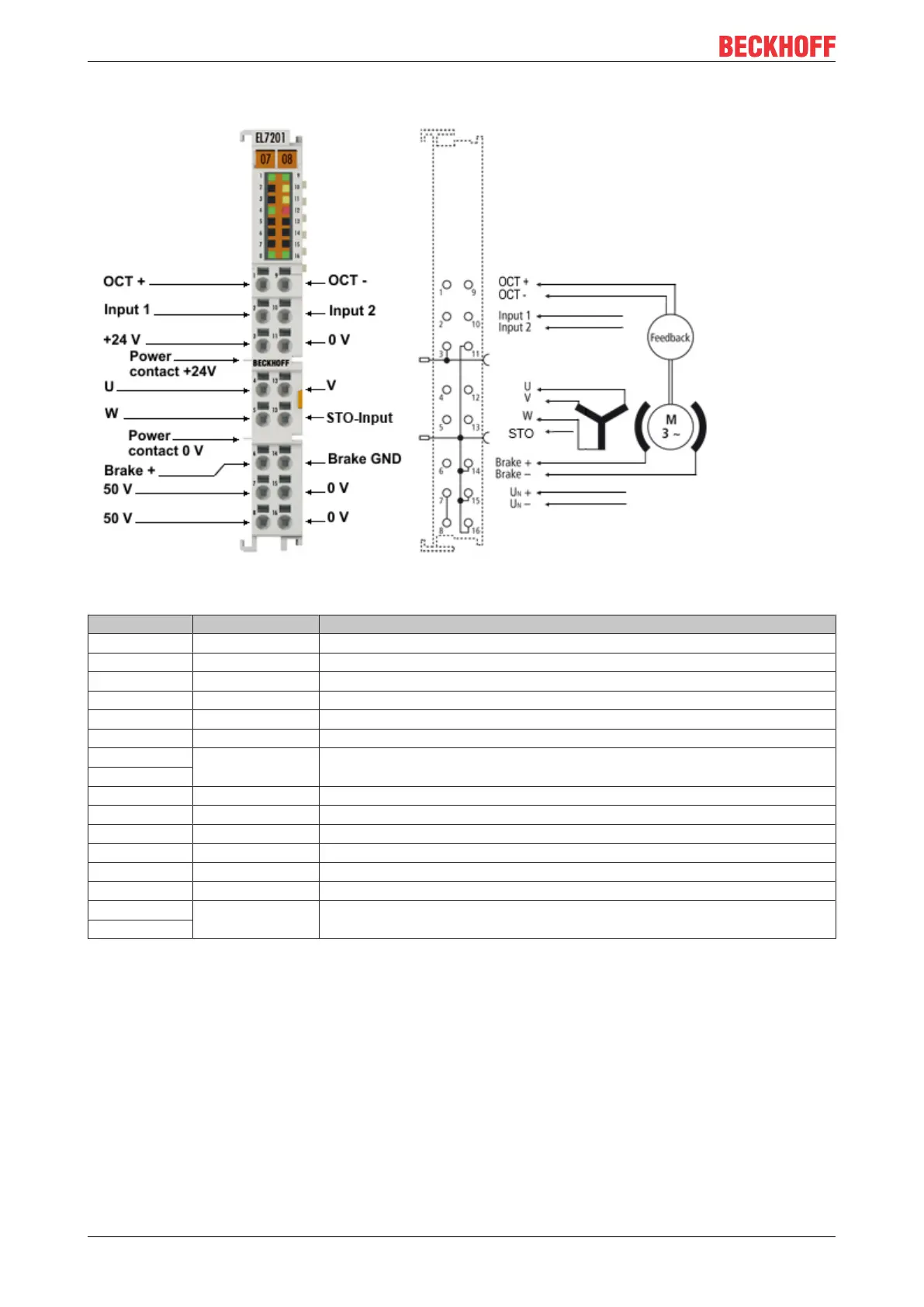
Connection
Fig.41: EL7201-901x Connection
Terminal point Name Comment
1 OCT + Positive input of the absolute feedback
2 Input 1 Digital input 1
3 +24 V Power contact +24 V
4 U Motor phase U
5 W Motor phase W
6 Brake + Motor brake +
7 50 V DC link supply + (8...50 V)
8
9 OCT - Negative input of the absolute feedback
10 Input 2 Digital input 2
11 0 V Power contact 0 V
12 V Motor phase V
13 STO input Input for STO signal (24 V)
14 Brake GND Motor brake 0V
15 0 V DC link 0V supply
16

 Loading...


